
Understanding GPIO Pins in 8051 Microcontroller
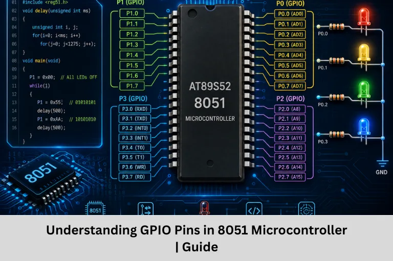
Learn GPIO pins in the 8051 microcontroller, including ports, input-output operation, LED interfacing, switch control, and embedded C examples.
- Understanding GPIO Pins in 8051 Microcontroller
-
Introduction: Understanding GPIO in the 8051 Microcontroller
- What Are GPIO Pins?
- GPIO Ports in 8051 Microcontroller
- How Do GPIO Pins Work in 8051?
- Detailed Study of Each 8051 GPIO Port
- GPIO Interfacing Examples in 8051
- GPIO with Delay Example: LED Blinking
- GPIO Block Diagram of 8051
- Important Points to Remember About 8051 GPIO
- Applications of GPIO in 8051 Microcontroller
- Advantages of GPIO in 8051
- Frequently Asked Questions (FAQs)
- Conclusion
Introduction: Understanding GPIO in the 8051 Microcontroller
General Purpose Input/Output (GPIO) pins are one of the most important building blocks of embedded systems programming. They act as the communication link between a microcontroller and the external hardware connected to it. Using GPIO pins, a microcontroller can read input signals from switches and sensors or control output devices such as LEDs, buzzers, relays, and displays.
The 8051 microcontroller is one of the most popular platforms for beginners learning embedded systems and microcontroller programming. Its simple architecture and four 8-bit I/O ports make it easier to understand important concepts such as digital input and output, port configuration, GPIO interfacing, embedded C programming, and hardware control.
In the 8051 microcontroller, GPIO ports are used to interact with the real world. For example, an LED can be switched ON or OFF by controlling a port pin, while a push button can be connected to a GPIO pin to detect user input. Understanding 8051 GPIO pins, port registers, input-output configuration, and digital signal control is therefore an essential step for anyone beginning a career in embedded systems design.
In this article, we will explore the GPIO pins of the 8051 microcontroller, understand the working of its four ports, study input and output operations, and look at practical examples such as LED interfacing and switch control.
What Are GPIO Pins?
GPIO stands for General Purpose Input/Output. GPIO pins are programmable digital pins that can be configured to perform different functions depending on the application.
A GPIO pin can generally work as:
Input Pin
An input pin is used to read signals from external devices.
Examples:
- Push buttons
- Switches
- Digital sensors
- External control signals
Output Pin
An output pin is used to send digital signals to external devices.
Examples:
- LEDs
- Buzzers
- Relays
- Digital displays
In the 8051 microcontroller, GPIO pins are grouped together into ports. Each port contains eight pins and can be controlled using the corresponding port register.
GPIO Ports in 8051 Microcontroller
The standard 8051 microcontroller has four 8-bit I/O ports. Each port contains eight GPIO pins.
| Port | Pins | Description |
|---|---|---|
| Port 0 (P0) | P0.0 – P0.7 | Dual-purpose I/O and Address/Data bus |
| Port 1 (P1) | P1.0 – P1.7 | General-purpose I/O |
| Port 2 (P2) | P2.0 – P2.7 | I/O and high-order address bus |
| Port 3 (P3) | P3.0 – P3.7 | I/O and special functions |
Total GPIO Pins in 8051
The 8051 has:
4 ports × 8 pins = 32 GPIO pins
These pins provide the microcontroller with the ability to interface with a wide range of external hardware.
How Do GPIO Pins Work in 8051?
The working of GPIO pins in the 8051 mainly depends on whether the pin is being used for input or output operation.
1. GPIO Output Operation
To use an 8051 port as an output, a logic value is written to the port.
Writing Logic 1
Writing 1 to a port pin makes the pin HIGH.
P1 = 0xFF;This makes all Port 1 pins HIGH.
Writing Logic 0
Writing 0 to a port pin makes the pin LOW.
P1 = 0x00;This makes all Port 1 pins LOW.
2. GPIO Input Operation
To use a port pin as an input in the 8051, a logic 1 is first written to the pin. The pin can then be read to detect the external signal.
P1 = 0xFF;

if (P1 & 0x01)
{
    // Switch is HIGH
}
In this example, P1.0 is checked to determine whether the input signal is HIGH.
Important Input Configuration Rule
In the 8051, always write 1 to a port pin before using it as an input. This is an important concept in 8051 port programming.
Detailed Study of Each 8051 GPIO Port
Port 0 (P0)
Port 0 consists of pins P0.0 to P0.7.
Features of Port 0
- It does not have internal pull-up resistors.
- External pull-up resistors are required when used as a general-purpose I/O port.
- It can be used for general input and output operations.
- It also functions as a multiplexed address/data bus.
Port 0 is commonly used in applications involving external memory interfacing.
Port 1 (P1)
Port 1 contains pins P1.0 to P1.7.
Features of Port 1
- It has internal pull-up resistors.
- It is used as a general-purpose I/O port.
- It does not have alternate functions in the standard 8051.
- It is commonly used for beginner-level GPIO experiments.
Because of its simple operation, Port 1 is frequently used for LED and switch interfacing.
Port 2 (P2)
Port 2 consists of pins P2.0 to P2.7.
Features of Port 2
- It has internal pull-up resistors.
- It can be used as a general-purpose I/O port.
- It acts as the high-order address bus during external memory access.
This makes Port 2 useful for both GPIO control and external memory interfacing.
Port 3 (P3)
Port 3 contains pins P3.0 to P3.7.
Special Functions of Port 3
| Pin | Alternate Function |
|---|---|
| P3.0 | RXD – Serial Input |
| P3.1 | TXD – Serial Output |
| P3.2 | INT0 – External Interrupt 0 |
| P3.3 | INT1 – External Interrupt 1 |
| P3.4 | T0 – Timer 0 External Input |
| P3.5 | T1 – Timer 1 External Input |
| P3.6 | WR – External Data Memory Write Control |
| P3.7 | RD – External Data Memory Read Control |
Why Is Port 3 Important?
Port 3 is important because its pins support both GPIO operations and alternate microcontroller functions. Developers must understand the selected function before using a Port 3 pin in an embedded application.
GPIO Interfacing Examples in 8051
1. LED Interfacing Using GPIO
An LED can be connected to an 8051 GPIO pin through a current-limiting resistor.
In many 8051 LED circuits, the LED is connected in an active LOW configuration.
- Logic HIGH → LED OFF
- Logic LOW → LED ON
P1 = 0x00;This can turn ON all LEDs connected to Port 1 in an active LOW circuit.
2. Switch Interfacing Using GPIO
A switch can be connected to a GPIO pin to provide digital input to the 8051.
if (P1 & 0x01)
{
    P2 = 0x00;
}
In this example, the microcontroller checks the input at P1.0 and controls Port 2 based on the switch condition.
GPIO with Delay Example: LED Blinking
LED blinking is one of the simplest and most useful 8051 GPIO programming examples.
8051 LED Blinking Program
#include <reg51.h>

void delay()
{
    int i, j;

    for(i = 0; i < 1000; i++)
        for(j = 0; j < 100; j++);
}

void main()
{
    while(1)
    {
        P1 = 0x00;  // LED ON
        delay();

        P1 = 0xFF;  // LED OFF
        delay();
    }
}
How This Program Works
The program continuously writes 0x00 and 0xFF to Port 1. The delay function creates a time gap between the two operations.
As a result, the LED repeatedly turns ON and OFF, creating a blinking effect.
What Can You Learn from This Example?
This simple program helps beginners understand:
- 8051 port programming
- GPIO output control
- Embedded C syntax
- Delay generation
- Digital signal control
- Basic hardware interfacing
GPIO Block Diagram of 8051
The basic GPIO operation of the 8051 can be understood using the following flow:
Microcontroller Program → Port Register → GPIO Pin → External Hardware
For input operation:
External Hardware → GPIO Pin → Port Register → Microcontroller Program
This shows how the 8051 communicates with external devices using its GPIO ports.
Important Points to Remember About 8051 GPIO
- Port 0 requires external pull-up resistors for general-purpose I/O.
- Writing
1to a port pin makes it ready for input operation. - Port 3 pins have dual functionality.
- Always use a current-limiting resistor with LEDs.
- Understand active HIGH and active LOW logic.
- Port registers are used to control GPIO pins.
- GPIO is the foundation of 8051 hardware interfacing.
Applications of GPIO in 8051 Microcontroller
GPIO pins are used in several embedded applications, including:
- LED control systems
- Switch-based control systems
- Sensor interfacing
- Display interfacing
- Keypad interfacing
- Buzzer control
- Relay control
- Industrial automation systems
Advantages of GPIO in 8051
The GPIO architecture of the 8051 offers several advantages:
- Simple to understand and use
- Flexible input and output configuration
- Supports multiple external devices
- Easy hardware interfacing
- Ideal for embedded systems beginners
- Useful for learning microcontroller programming
Frequently Asked Questions (FAQs)
How many GPIO pins are available in the 8051 microcontroller?
The standard 8051 microcontroller has four 8-bit ports, providing a total of 32 GPIO pins. These ports are Port 0, Port 1, Port 2, and Port 3.
Which 8051 port does not have internal pull-up resistors?
Port 0 does not have internal pull-up resistors. External pull-up resistors are required when Port 0 is used for general-purpose input/output operations.
How do you configure an 8051 GPIO pin as an input?
To configure an 8051 GPIO pin for input operation, write logic 1 to the required pin first. After that, the pin value can be read to detect the external input signal.
Why is Port 3 special in the 8051 microcontroller?
Port 3 is special because its pins support both general-purpose I/O and alternate functions. These include UART communication, external interrupts, timer inputs, and external memory control signals.
What is the simplest project to learn 8051 GPIO programming?
LED blinking is one of the simplest projects for learning 8051 GPIO programming. It helps beginners understand port control, digital output, delay functions, and basic embedded C programming.
Conclusion
GPIO pins are the foundation of 8051 microcontroller programming and embedded hardware interfacing. They allow the microcontroller to communicate directly with external devices such as LEDs, switches, sensors, displays, and control systems. By learning how to configure 8051 GPIO ports, port registers, digital input and output, and embedded C programs, beginners can build a strong foundation in embedded systems
Understanding the differences between Port 0, Port 1, Port 2, and Port 3 is especially important because each port has unique features and functions. While Port 0 requires external pull-up resistors, Port 3 provides additional functions such as UART communication, external interrupts, and timer inputs.
From a simple LED blinking project to advanced sensor and industrial control applications, GPIO knowledge plays a vital role in microcontroller programming, digital electronics, embedded system design, and hardware interfacing. Once you master GPIO concepts, you can confidently move on to advanced topics such as timers, interrupts, serial communication, and real-time embedded applications.
Author: ETDA Trainers
Experience: 10+ Years of Industry Experience in Embedded Systems, IoT, and Embedded C Programming