
Electronics Design and Simulation Techniques: Complete Guide for Beginners
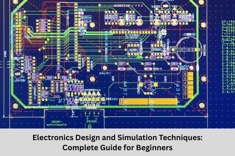
Learn electronics design and simulation techniques including schematic design, PCB layout, SPICE simulation, signal integrity, thermal analysis, and industry tools. Discover career opportunities with Embedded Tech Development Academy (ETDA).
- Electronics Design and Simulation Techniques: Complete Guide for Beginners
-
Electronics Design and Simulation Techniques: From Concept to Validation
- Introduction
- Electronics Design Flow
- Schematic Design Fundamentals
- Simulation Techniques
- PCB Design Considerations
- Advanced Simulation Methods
- Component Modeling
- Design Verification
- Industry Standard Electronics Design Tools
- Practical Design Challenges
- Emerging Technologies
- Career Opportunities in Electronics Design
- Why Learn Electronics Design at Embedded Tech Development Academy (ETDA)?
- Frequently Asked Questions (FAQs)
- Conclusion
Electronics Design and Simulation Techniques: From Concept to Validation
Introduction
The rapid evolution of modern electronics has transformed industries ranging from consumer gadgets and automotive systems to industrial automation, healthcare, aerospace, telecommunications, and embedded systems. Behind every successful electronic product lies a well-planned design process that combines creativity, engineering principles, and advanced simulation techniques. Electronics design is no longer limited to drawing circuit diagrams—it involves circuit simulation, PCB design, signal integrity analysis, power electronics, thermal management, electromagnetic compatibility (EMC), component selection, and design verification before manufacturing.
Simulation tools have become an indispensable part of electronics development because they help engineers identify design flaws early, optimize circuit performance, reduce development costs, and significantly shorten product development cycles. Whether designing a simple amplifier, an Internet of Things (IoT) device, a high-speed communication system, or a complex embedded controller, simulation enables engineers to validate their ideas without building multiple physical prototypes.
For aspiring engineers, mastering electronics circuit design, PCB layout, SPICE simulation, electronic circuit analysis, analog and digital electronics, embedded hardware design, and electronic product development opens the door to rewarding careers in semiconductor companies, automotive electronics, consumer electronics, robotics, Internet of Things (IoT), and industrial automation.
At Embedded Tech Development Academy (ETDA), students receive industry-oriented training in electronics design and simulation through hands-on laboratory sessions, real-world projects, PCB design practice, and simulation-based learning. Embedded Tech Development Academy (ETDA)‘s practical approach, experienced trainers, and assured placement support help students gain the technical skills and confidence required to excel in today’s competitive electronics industry.
In this comprehensive guide, you’ll explore the complete electronics design flow, popular simulation techniques, PCB design considerations, industry-standard tools, and emerging technologies shaping the future of electronics engineering.
Electronics Design Flow
Modern electronics design follows a systematic workflow that converts ideas into fully functional electronic products.
Key Design Stages
- Requirement Analysis
- Schematic Design
- Component Selection
- Circuit Simulation
- PCB Layout Design
- Prototype Development
- Testing and Validation
- Performance Optimization
- Manufacturing
Schematic Design Fundamentals
A schematic represents the logical connection between electronic components.
Essential Design Elements
| Element | Purpose | Key Considerations |
|---|---|---|
| Power Supply | Voltage regulation | Ripple, efficiency |
| Signal Path | Data transfer | Impedance matching |
| Grounding | Return current path | Star grounding, Ground plane |
| Decoupling | Noise suppression | Capacitor placement |
Common Circuit Building Blocks
Power Supply Circuits
Provide regulated voltage to the system.
Amplifier Circuits
Increase signal strength.
Oscillator Circuits
Generate clock signals.
Filter Circuits
Remove unwanted frequencies.
Microcontroller Interface Circuits
Connect sensors, displays, communication modules, and actuators.
Simulation Techniques
Simulation helps engineers verify circuit functionality before hardware development.
Types of Circuit Simulation
| Simulation | Purpose | Common Tools |
|---|---|---|
| DC Analysis | Bias point calculation | SPICE |
| AC Analysis | Frequency response | Multisim |
| Transient Analysis | Time-domain response | LTspice |
| Monte Carlo Analysis | Component tolerance analysis | PSpice |
SPICE Netlist Example
* RC Low Pass Filter
V1 1 0 DC 5 AC 1
R1 1 2 1k
C1 2 0 1uF
.ac dec 10 1 1Meg
.end
PCB Design Considerations
PCB layout greatly influences circuit reliability and performance.
High-Speed PCB Design Rules
Controlled Impedance
Maintain constant impedance for high-frequency signals.
Length Matching
Critical for differential pair routing.
Trace Routing
Avoid sharp 90-degree bends.
Ground Plane Design
Use continuous ground planes to reduce EMI.
Power Distribution
- Wide power traces
- Low impedance return paths
- Proper decoupling capacitor placement
- Star power routing
PCB Stack-up
| Layers | Applications | Cost |
|---|---|---|
| 2 Layer | Simple circuits | Low |
| 4 Layer | Embedded systems | Medium |
| 6+ Layer | High-speed digital systems | High |
Advanced Simulation Methods
Signal Integrity Analysis
Signal integrity ensures reliable communication between components.
Important parameters include:
- Rise Time
- Fall Time
- Crosstalk
- Reflection
- Propagation Delay
- Eye Diagram
- Impedance Matching
Popular tools include:
- HyperLynx
- Cadence Sigrity
- Keysight ADS
Thermal Simulation
Thermal analysis prevents overheating.
Heat Transfer Equation
Q = hA(Tsurface − Tambient) + εσA(Tsurface⁴ − Tambient⁴)
Factors affecting temperature include:
- Heat sink design
- Copper thickness
- Airflow
- Component placement
Component Modeling
Simulation accuracy depends on component models.
Model Types
| Model | Accuracy | Speed |
|---|---|---|
| Behavioral | Low | Fast |
| Macro Model | Medium | Moderate |
| Physical Model | High | Slow |
Custom Modeling
Languages such as Verilog-A allow engineers to build custom electronic device models for simulation.
Design Verification
Verification ensures the design satisfies electrical and manufacturing requirements.
Verification Methods
| Method | Purpose |
|---|---|
| ERC | Electrical Rule Check |
| DRC | Design Rule Check |
| LVS | Layout versus Schematic |
Tolerance Analysis
Tolerance analysis predicts circuit performance considering manufacturing variations.
Common methods include:
- Worst-case analysis
- Monte Carlo simulation
- Statistical analysis
Industry Standard Electronics Design Tools
Commercial Software
| Software | Schematic | Simulation | PCB |
|---|---|---|---|
| Altium Designer | ✔ | ✔ | ✔ |
| Cadence | ✔ | ✔ | ✔ |
| Mentor Graphics | ✔ | ✔ | ✔ |
Open Source Tools
- KiCad
- LTspice
- ngspice
- Fritzing
These tools are widely used by students and professionals.
Practical Design Challenges
EMI Issues
Poor PCB layout often results in electromagnetic interference.
Solutions include:
- Proper grounding
- Shielding
- Ferrite beads
- EMI filters
Thermal Problems
High-power devices require:
- Heat sinks
- Thermal vias
- Copper pours
- Air cooling
Signal Integrity Problems
Common issues include:
- Crosstalk
- Reflection
- Ringing
- Timing errors
Manufacturing Challenges
Designs must satisfy Design for Manufacturing (DFM) guidelines.
Critical checks include:
- Minimum trace width
- Hole sizes
- Solder mask clearance
- Silkscreen readability
Emerging Technologies
AI-Assisted Electronics Design
Artificial Intelligence now assists engineers by:
- Automatic routing
- Component placement
- Failure prediction
- Design optimization
Cloud-Based Simulation
Cloud platforms enable:
- Faster simulations
- Team collaboration
- Shared component libraries
- Parallel processing
Multi-Physics Simulation
Modern electronics increasingly require combined analysis of:
- Electrical behavior
- Thermal performance
- Mechanical stress
- Electromagnetic compatibility
Career Opportunities in Electronics Design
Professionals skilled in electronics design and simulation are highly sought after.
Popular Job Roles
- Electronics Design Engineer
- PCB Design Engineer
- Hardware Design Engineer
- Embedded Systems Engineer
- VLSI Design Engineer
- Power Electronics Engineer
- Analog Design Engineer
- Signal Integrity Engineer
- EMC Engineer
- R&D Engineer
Industries hiring these professionals include automotive, aerospace, Internet of Things (IoT), robotics, telecommunications, healthcare, consumer electronics, semiconductor manufacturing, and industrial automation.
Why Learn Electronics Design at Embedded Tech Development Academy (ETDA)?
Industry-Oriented Electronics Training
Embedded Tech Development Academy (ETDA) provides comprehensive training in electronics design and simulation, enabling students to develop practical hardware design skills using industry-standard software and laboratory equipment.
Benefits of Learning at ETDA
Practical Hands-on Training
Students design, simulate, build, and test real electronic circuits.
Industry Software Exposure
Hands-on experience with PCB design, SPICE simulation, and embedded hardware development.
Project-Based Learning
Students complete real-world electronics projects to strengthen practical knowledge.
Assured Placement Support
ETDA offers assured placement support, including resume preparation, mock interviews, aptitude training, and technical interview guidance to help students launch successful careers in electronics and embedded systems.
Frequently Asked Questions (FAQs)
What is electronics design?
Electronics design is the process of creating, simulating, testing, and validating electronic circuits and hardware before manufacturing.
Why is circuit simulation important?
Circuit simulation helps identify design errors, optimize performance, reduce development costs, and minimize hardware prototyping.
Which software is commonly used for electronics design?
Popular tools include Altium Designer, Cadence, LTspice, KiCad, Multisim, PSpice, ngspice, and Mentor Graphics.
What skills are required to become an electronics design engineer?
Key skills include analog and digital electronics, PCB design, SPICE simulation, embedded systems, signal integrity analysis, component selection, and troubleshooting.
Where can I learn electronics design with practical projects and placement support?
You can learn electronics design and simulation at Embedded Tech Development Academy (ETDA), where industry-oriented training, real-time projects, expert mentorship, and assured placement support prepare students for successful careers in electronics, embedded systems, Internet of Things (IoT), semiconductor, and hardware design industries.
Conclusion
Electronics design has evolved into a multidisciplinary engineering field that combines analog circuit design, digital electronics, PCB layout, embedded systems, SPICE simulation, signal integrity analysis, thermal management, power electronics, EMI/EMC compliance, and electronic product validation. Modern simulation tools allow engineers to verify circuit functionality, optimize performance, and minimize costly design iterations before manufacturing, resulting in faster product development and improved reliability.
As emerging technologies such as Artificial Intelligence, Internet of Things (IoT), automotive electronics, robotics, wireless communication, Industry 4.0, and smart embedded systems continue to advance, the demand for skilled electronics design engineers is growing rapidly across industries worldwide.
For students and professionals seeking to build expertise in electronics hardware design, Embedded Tech Development Academy (ETDA) offers industry-focused training with practical circuit design, simulation, PCB development, and real-time projects. Supported by experienced mentors and assured placement support, Embedded Tech Development Academy (ETDA) equips learners with the technical knowledge and practical experience required to succeed in today’s competitive electronics and embedded systems industry.
Author: ETDA Trainers
Experience: 10+ Years of Industry Experience in Embedded Systems, IoT, and Embedded C Programming