
Clipper and Clamper Circuits: Working, Types, Applications & Waveform Shaping | ETDA
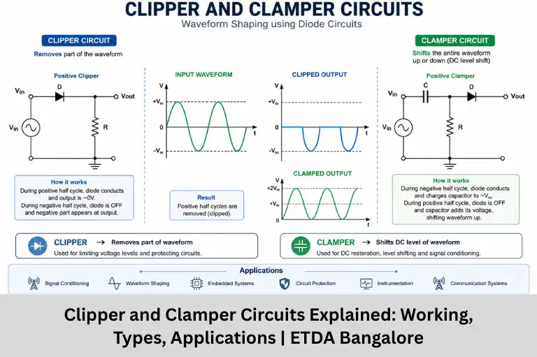
Learn Clipper and Clamper Circuits, their working principles, types, diode configurations, applications, waveform shaping techniques, and practical examples. Master analog electronics with Embedded Tech Development Academy (ETDA), the Top Embedded Training Institute in Bangalore.
- Clipper and Clamper Circuits: Working, Types, Applications & Waveform Shaping | ETDA
-
Clipper and Clamper Circuits: Mastering Waveform Shaping
- 1. Introduction to Waveform Modification Circuits
- 2. Clipper Circuits (Voltage Limiters)
- 3. Clamper Circuits (DC Restorers)
- 4. Design Considerations
- 5. Practical Implementations
- 6. Signal Processing Applications
- 7. Troubleshooting Guide
- 8. Advanced Concepts
- 9. Simulation Examples
- 10. Future Developments
-
FAQs
- What is the difference between a clipper circuit and a clamper circuit?
- What are the applications of clipper and clamper circuits?
- Which diode is commonly used in clipper circuits?
- Why is a capacitor important in a clamper circuit?
- Where can I learn practical analog electronics and embedded hardware design?
- Conclusion
Clipper and Clamper Circuits: Mastering Waveform Shaping
In analog electronics, controlling and modifying electrical waveforms is essential for ensuring reliable circuit operation and protecting sensitive electronic components. Clipper and Clamper circuits are two of the most fundamental waveform shaping circuits used to alter voltage signals without significantly changing their original waveform characteristics. These circuits are widely employed in signal conditioning, voltage limiting, DC level shifting, communication systems, embedded systems, power electronics, and electronic instrumentation.
A clipper circuit removes or “clips” portions of an input waveform that exceed a specified voltage level, while a clamper circuit shifts the entire waveform to a desired DC level without changing its peak-to-peak amplitude. Together, these circuits improve signal quality, protect integrated circuits from voltage spikes, and ensure proper operation of analog and digital systems. Whether you’re designing microcontroller-based systems, PCB circuits, Internet of Things (IoT) devices, or communication hardware, understanding clipper and clamper circuits is essential for building robust electronic products.
These circuits are extensively used in ADC input protection, television synchronization, audio signal processing, RF communication, medical electronics, industrial automation, and digital logic interfaces. Their simplicity, low cost, and effectiveness make them indispensable in both educational laboratories and commercial electronic products.
At Embedded Tech Development Academy (ETDA), recognized as the Top Embedded Training Institute in Bangalore, students receive hands-on training in analog electronics, embedded systems, PCB design, microcontrollers, Internet of Things (IoT), and waveform analysis using industry-standard tools. Learning practical circuits like clipper and clamper circuits helps aspiring engineers develop the hardware design skills required by today’s electronics, semiconductor, and embedded industries.
LSI Keywords: waveform shaping circuits, analog electronics, diode clipper circuit, clamper circuit, voltage limiter, voltage clamping, signal conditioning, analog signal processing, electronic circuit design, embedded systems, PCB design, microcontroller interface, communication electronics, hardware design, analog circuit analysis.
1. Introduction to Waveform Modification Circuits
Clipper and clamper circuits are essential electronic circuits used to modify signal waveforms without distorting their basic shape. These analog processing blocks serve critical functions in communication systems, power electronics, and signal conditioning.
Key Applications
- Signal conditioning for ADC inputs
- Noise elimination in communication systems
- DC restoration in TV/video signals
- Voltage protection for sensitive components
- Pulse shaping in digital systems
2. Clipper Circuits (Voltage Limiters)
2.1 Basic Clipper Types
D
Vin —-|>|—–+—— Vout
|
R
|
GND
2.2 Diode Clipper Operation
Positive Series Clipper
Input → [Diode Anode→Cathode] → Output
↑
Vref (for biased clippers)
Transfer Characteristic
- Vout = Vin when Vin < Vref + Vd
- Vout = Vref + Vd when Vin ≥ Vref + Vd
2.3 Practical Clipper Configurations
| Type | Circuit Configuration | Output |
|---|---|---|
| Positive Parallel | Diode cathode connected to ground | Clips positive peaks |
| Negative Series | Reverse-biased diode connected in series | Blocks negative voltage |
| Biased Dual | Two diodes with DC voltage sources | Clips both positive and negative peaks |
Example – Noise Spike Clipper
- R = 1 kΩ
- D1/D2 = 1N4148
- Forward Voltage = 0.7V
- Clipping Level = ±0.7V
3. Clamper Circuits (DC Restorers)
3.1 Basic Clamper Operation
C
Vin ~ ──────||───────+──────── Vout
|
|
─|<|─ D
|
GND
|
R
|
GND
Negative Clamper Operation
- First positive half-cycle charges the capacitor.
- Capacitor stores charge.
- Remaining waveform shifts downward.
- Output DC level becomes −(Vp − Vd).
3.2 Types of Clampers
| Type | Components | DC Shift |
|---|---|---|
| Positive Clamper | Diode cathode connected to ground | Upward |
| Negative Clamper | Diode anode connected to ground | Downward |
| Biased Clamper | External DC voltage source | Controlled |
TV Synchronization Clamper
- Capacitor = 0.1 μF
- Diode = 1N914
- Resistor = 1 MΩ
Used to clamp synchronization pulses to the reference voltage.
4. Design Considerations
4.1 Component Selection Guide
| Parameter | Clipper | Clamper |
|---|---|---|
| Diode | Fast switching (1N4148) | Low leakage (1N914) |
| Capacitor | Not required | XC << R at minimum frequency |
| Resistor | Current limiting | RC discharge constant |
| Reference Voltage | Stable source | Precision bias source |
4.2 Frequency Response Analysis
Clipper Bandwidth
- Limited by diode switching speed
- Typical bandwidth: 10–100 MHz
Clamper Low-Frequency Limit
fmin = 1 / (2πRC)
Where RC should be much larger than the input signal period.
5. Practical Implementations
5.1 Zener Clipper Circuit
Voltage Limiter Design
- Clips voltage at Zener breakdown voltage.
- Used for over-voltage protection.
Power Rating:
Pz > (Vinmax − Vz)² / R
5.2 Precision Active Clipper
Operational Amplifier Implementation
Advantages:
- High precision clipping
- Adjustable clipping levels
- Eliminates diode forward voltage drop
6. Signal Processing Applications
6.1 Communication Systems
- AM demodulation
- Pulse slicing
- Receiver protection
6.2 Power Electronics
- MOSFET gate protection
- IGBT driver circuits
- Snubber circuits
6.3 Biomedical Instrumentation
- ECG amplifiers
- EMG systems
- Defibrillator protection
7. Troubleshooting Guide
7.1 Common Clipper Issues
| Problem | Cause | Solution |
|---|---|---|
| Distorted Output | High diode forward voltage | Use a Schottky diode |
| Slow Response | High capacitance | Reduce parasitic capacitance |
| Uneven Clipping | Diode mismatch | Use matched diodes |
7.2 Common Clamper Issues
| Problem | Cause | Solution |
|---|---|---|
| DC Drift | Capacitor leakage | Replace the capacitor |
| Waveform Tilt | Small RC time constant | Increase the resistor or capacitor value |
| No Clamping | Incorrect diode direction | Reverse the diode orientation |
8. Advanced Concepts
8.1 MOSFET-Based Clippers
Advantages
- Lower losses
- Faster switching
- Suitable for high-frequency circuits
8.2 Adaptive Clamping
Benefits
- Automatic threshold adjustment
- Improved signal handling
- Better performance in variable input conditions
Applications include automotive electronics, industrial automation, and communication equipment.
9. Simulation Examples
9.1 LTspice Clipper Model
* Positive Negative Clipper
V1 1 0 SIN(0 5 1k)
D1 1 2 D1N4148
D2 0 2 D1N4148
R1 2 0 1k
.model D1N4148 D(Is=2.52n Rs=0.568 N=1.752 Cjo=4p M=0.4 tt=20n)
9.2 MATLAB Clamper Simulation
t = 0:0.0001:0.01;
Vin = 5*square(2*pi*100*t);
Vout = Vin – 4.3;
plot(t,Vin,t,Vout);
10. Future Developments
10.1 Integrated Protection Circuits
- On-chip protection
- MEMS voltage limiters
- Intelligent clamping circuits
10.2 Photonic Clippers
- Optical diode technology
- Laser threshold devices
- Ultra-high-frequency waveform processing
FAQs
What is the difference between a clipper circuit and a clamper circuit?
A clipper circuit removes unwanted portions of a waveform above or below a specified voltage level, while a clamper circuit shifts the entire waveform to a different DC level without changing its peak-to-peak value.
What are the applications of clipper and clamper circuits?
They are used in signal conditioning, ADC protection, communication systems, television receivers, medical instrumentation, power electronics, embedded systems, and industrial automation.
Which diode is commonly used in clipper circuits?
Small-signal diodes such as 1N4148, 1N914, Schottky diodes, and Zener diodes are commonly used depending on the application and required clipping voltage.
Why is a capacitor important in a clamper circuit?
The capacitor stores electrical charge during one half-cycle and releases it during the next, creating the required DC voltage shift while maintaining the waveform shape.
Where can I learn practical analog electronics and embedded hardware design?
You can learn through hands-on projects at Embedded Tech Development Academy (ETDA), the Top Embedded Training Institute in Bangalore, where industry-focused training covers analog electronics, embedded systems, PCB design, IoT, and real-time hardware development with placement support.
Conclusion
Clipper and clamper circuits are among the most important building blocks of analog electronics, enabling engineers to shape, protect, and condition electrical waveforms for a wide range of applications. From communication systems and embedded hardware to medical devices, consumer electronics, and industrial automation, these circuits improve signal integrity, eliminate unwanted voltage levels, and safeguard sensitive components from electrical damage.
As embedded systems continue to evolve with technologies such as Internet of Things (IoT), AI-enabled hardware, automotive electronics, and wireless communication, the demand for engineers who understand waveform shaping, analog circuit design, and electronic signal processing continues to grow. Mastering clipper and clamper circuits also builds a strong foundation for advanced topics including operational amplifiers, power electronics, analog-to-digital conversion, PCB design, and electronic product development.
At Embedded Tech Development Academy (ETDA), the Top Embedded Training Institute in Bangalore, students gain practical experience in analog electronics, digital electronics, embedded C programming, microcontrollers, ARM processors, PCB design, Internet of Things (IoT), and real-time embedded projects. Through industry-oriented training, modern laboratories, and placement-focused programs, Embedded Tech Development Academy (ETDA) prepares aspiring engineers for successful careers in electronics, embedded systems, semiconductor design, and automation.
Whether you’re a student beginning your electronics journey or a professional looking to strengthen your hardware design skills, understanding clipper and clamper circuits is an essential step toward mastering analog circuit design and developing reliable, high-performance electronic systems.
LSI Keywords: waveform shaping, diode clipper circuit, voltage limiter circuit, DC restoration, analog signal processing, embedded hardware design, PCB layout, electronic circuit analysis, analog electronics course, microcontroller hardware, communication electronics, electronics design, embedded systems training, Top Embedded Training Institute in Bangalore.
Author: ETDA Trainers
Experience: 10+ Years of Industry Experience in Embedded Systems, IoT, and Embedded C Programming