
GPS Module Interfacing with LPC1768: Circuit, UART & Code | ETDA
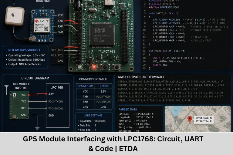
Learn GPS module interfacing with LPC1768 using UART1, NMEA parsing, latitude and longitude extraction, C code, applications, FAQs, and practical tips.
- GPS Module Interfacing with LPC1768: Circuit, UART & Code | ETDA
-
GPS Module Interfacing with LPC1768: Complete Guide
- Introduction to GPS Module Interfacing with LPC1768
- What Is a GPS Module?
- SKG13BL GPS Module Overview
- LPC1768 and GPS Communication
- GPS Module to LPC1768 Interfacing
- UART1 Initialization for GPS
- Receiving GPS Data Through UART1
- Understanding NMEA GPS Data
- GGA vs RMC Sentences
- GPS Data Parsing Algorithm
- GPS Interfacing Flow
- Advantages of Using UART for GPS Interfacing
- Disadvantages and Limitations
- Applications of GPS and LPC1768
-
Practical Tips for Successful GPS Interfacing
- Verify Power Requirements
- Confirm UART Settings
- Check Pin Multiplexing
- Use a Buffer
- Validate the Fix
- Handle Communication Errors
- FAQs
- How is a GPS module interfaced with the LPC1768?
- What data does a GPS module send to the LPC1768?
- What is NMEA in GPS communication?
- Why is UART commonly used to interface GPS modules?
- What are the major challenges when interfacing GPS with LPC1768?
- Conclusion
GPS Module Interfacing with LPC1768: Complete Guide
Introduction to GPS Module Interfacing with LPC1768
Location tracking has become an important part of modern embedded systems. From vehicle navigation and fleet management to asset tracking, Internet of Things (IoT) devices, emergency services, and location-based applications, embedded systems increasingly need accurate positioning information. A GPS module provides a convenient way for a microcontroller to obtain information such as latitude, longitude, altitude, speed, date, and time from satellite signals.
One popular approach is to interface a GPS receiver such as the SKG13BL with the LPC1768 ARM Cortex-M3 microcontroller through a UART serial interface. The GPS receiver processes signals from navigation satellites and outputs positioning information in a standard text-based format known as NMEA (National Marine Electronics Association) protocol. The LPC1768 can receive these serial messages, identify relevant NMEA sentences such as GGA and RMC, parse the fields, and use the extracted location information in an embedded application.
GPS-to-microcontroller interfacing is a useful practical project for learning UART communication, serial communication, embedded C programming, NMEA protocol, GPS data parsing, interrupt-driven communication, microcontroller peripherals, real-time location tracking, and Internet of Things (IoT) -based tracking systems.
The LPC1768 is particularly suitable for such applications because it provides multiple serial interfaces and sufficient processing capability for receiving and processing continuous GPS data. GPS information can be displayed on an LCD, transmitted to another controller, stored in memory, or forwarded to an Internet of Things (IoT) gateway or wireless communication module.
For engineering students, implementing GPS interfacing is also an excellent way to understand how hardware and software interact in a real embedded system. Instead of learning UART only as a theoretical peripheral, students can use a real GPS receiver to observe serial data, develop a parser, handle communication errors, and convert raw NMEA fields into meaningful geographic coordinates.
Embedded Tech Development Academy (ETDA) focuses on practical embedded systems education where learners can work with microcontrollers, communication interfaces, sensors, Internet of Things (IoT) technologies, and real-world projects. For students searching for the Top Embedded Training Institute in Bangalore, Embedded Tech Development Academy (ETDA) provides hands-on training designed to strengthen embedded programming skills and practical implementation knowledge, along with career-focused learning and placement support.
What Is a GPS Module?
A GPS module is an electronic receiver that determines its position by receiving signals transmitted by navigation satellites.
A GPS receiver can provide information such as:
- Latitude
- Longitude
- Altitude
- Speed
- UTC time
- Date
- Number of satellites
- Fix quality
- Course or direction
The receiver processes satellite signals internally and makes the resulting information available to an external controller through interfaces such as UART.
GPS Module Output
Many GPS modules provide positioning information using NMEA sentences.
A typical sentence may look like:
$GPGGA,123519,4807.038,N,01131.000,E,1,08,0.9,545.4,M,46.9,M,,*47The exact sentence prefixes can vary depending on the receiver and GNSS constellation being used.
SKG13BL GPS Module Overview
The SKG13BL is a compact GPS receiver module designed for embedded positioning applications. The module uses a MediaTek MT3337-series GPS engine and provides positioning information through a serial interface.
Key Features
- High sensitivity
- Low power consumption
- UART serial interface
- NMEA-compatible output
- 1PPS timing output
- Compact form factor
- Configurable communication parameters on supported versions
Typical NMEA Sentences
Common positioning-related sentences include:
- GGA – Fix information, altitude, satellites, and coordinates
- RMC – Recommended minimum navigation data
- GSA – DOP and satellite information
- GSV – Satellites in view
GPS Applications
GPS modules are commonly used in:
- Vehicle tracking
- Fleet management
- Navigation systems
- Asset tracking
- Internet of Things (IoT) devices
- Personal tracking systems
- Agriculture applications
- Location-based services
- Robotics
- Embedded monitoring systems
LPC1768 and GPS Communication
The LPC1768 is an ARM Cortex-M3-based microcontroller with multiple UART peripherals. These UART interfaces make it convenient to communicate with GPS receivers, GSM modules, Bluetooth modules, PCs, and other serial devices.
A GPS module generally sends data through its TX pin, while the microcontroller receives that information through its corresponding UART RX pin.
UART Communication
UART stands for Universal Asynchronous Receiver/Transmitter.
UART communication typically uses:
- TX
- RX
- GND
For a simple GPS receiver connection, the GPS TX line is connected to the microcontroller’s UART RX line.
Important Pin-Mapping Note
The exact LPC1768 pin mapping depends on the selected UART function and the device’s PINSEL configuration.
For example, the supplied code uses:
LPC_PINCON->PINSEL0 |= (1<<16) | (1<<18);which corresponds to a particular UART1 pin configuration on the LPC1768. Therefore, the physical GPS wiring must match the UART1 RX/TX pins selected by the PINSEL settings.
General Connection Rule
The most important rule is:
GPS TX → LPC1768 UART RX
and, when two-way communication is required:
GPS RX → LPC1768 UART TX
Also connect:
GPS GND → LPC1768 GND
Always verify the module’s operating voltage and I/O voltage requirements before connecting it to the microcontroller.
GPS Module to LPC1768 Interfacing
Example UART Connection
| GPS Module | LPC1768 UART | Function |
|---|---|---|
| TX | Selected UART1 RX pin | GPS data to LPC1768 |
| RX | Selected UART1 TX pin | Configuration commands from LPC1768 |
| GND | GND | Common ground |
| VCC | Appropriate supply | Module power |
For a receive-only GPS application, the GPS RX connection may not be required.
UART1 Initialization for GPS
The LPC1768 UART must be configured before GPS data can be received.
A basic UART initialization sequence includes:
- Configure the required pins using PINSEL.
- Configure the UART line format.
- Enable the divisor latch.
- Set the baud-rate divisor.
- Disable divisor-latch access.
- Begin receiving serial data.
Example UART1 Initialization Code
#include <LPC17xx.h>

void UART1_Init(void)
{
    /* Configure UART1 pins according to the selected pin mapping */
    LPC_PINCON->PINSEL0 |= (1 << 16) | (1 << 18);

    /* 8-bit data, 1 stop bit, no parity, DLAB = 1 */
    LPC_UART1->LCR = 0x83;

    /* Example divisor for the selected PCLK/baud configuration */
    LPC_UART1->DLL = 97;
    LPC_UART1->DLM = 0;

    /* DLAB = 0 */
    LPC_UART1->LCR = 0x03;
}
The baud-rate divisor should be calculated from the actual peripheral clock (PCLK) used by the LPC1768 configuration. A divisor value should not be assumed universally because the LPC17xx clock configuration can change PCLK.
Receiving GPS Data Through UART1
Once UART1 is configured, the LPC1768 can continuously receive characters from the GPS receiver.
UART Receive Function
A simple polling-based receive function can be written as:
char UART1_GetChar(void)
{
    while (!(LPC_UART1->LSR & 0x01));

    return LPC_UART1->RBR;
}
The LSR bit 0 indicates that received data is available.
How the Receive Process Works
The microcontroller:
- Waits for a character.
- Reads the received character.
- Stores it in a buffer.
- Detects the beginning of an NMEA sentence.
- Continues receiving characters.
- Detects the end of the sentence.
- Parses the received fields.
Polling vs Interrupt-Based Reception
Polling is easy to understand and useful for simple demonstrations. However, an interrupt-driven UART receiver is generally better for larger embedded applications because the CPU does not need to continuously wait for incoming characters.
Understanding NMEA GPS Data
GPS receivers commonly output positioning information using NMEA-formatted sentences.
A sentence begins with $ and contains comma-separated fields.
Example GGA Sentence
$GPGGA,123519,4807.038,N,01131.000,E,1,08,0.9,545.4,M,46.9,M,,*47This sentence contains several fields.
Important GGA Fields
| Field | Meaning |
|---|---|
| 123519 | UTC time |
| 4807.038 | Latitude |
| N | Latitude direction |
| 01131.000 | Longitude |
| E | Longitude direction |
| 1 | Fix quality |
| 08 | Number of satellites |
| 0.9 | HDOP |
| 545.4 | Altitude |
Understanding Coordinates
The latitude:
4807.038,Nrepresents:
48° 07.038′ N
The longitude:
01131.000,Erepresents:
11° 31.000′ E
For many mapping applications, these values may need to be converted from NMEA degrees-and-minutes format into decimal degrees.
GGA vs RMC Sentences
GGA Sentence
GGA provides information about:
- Position
- Fix quality
- Number of satellites
- HDOP
- Altitude
- UTC time
RMC Sentence
RMC provides useful navigation information such as:
- UTC time
- Position
- Validity status
- Speed
- Course
- Date
Which Sentence Should You Use?
For a basic location-tracking application, GGA and RMC are commonly useful.
Choosing the Right Data
If the application needs altitude and satellite/fix information, GGA is useful. If speed, course, date, and basic navigation data are required, RMC can be more convenient.
GPS Data Parsing Algorithm
A basic GPS parsing algorithm can follow these steps:
Step 1 – Initialize UART
Configure the selected LPC1768 UART at the GPS module’s configured baud rate.
Step 2 – Receive Characters
Read incoming characters continuously.
Step 3 – Detect Start of Sentence
Look for the $ character.
Step 4 – Store the Sentence
Store received characters in a buffer until the end-of-line characters are detected.
Step 5 – Identify the Sentence Type
Check whether the sentence contains:
- GGA
- RMC
- GSA
- GSV
Step 6 – Extract Required Fields
Separate the comma-delimited fields and extract latitude, longitude, time, speed, or other required parameters.
Step 7 – Validate Data
Check the fix status and, where appropriate, validate the NMEA checksum before using the coordinates.
Step 8 – Display or Transmit
The extracted information can be:
- Displayed on an LCD
- Sent to a PC
- Stored in memory
- Sent through GSM
- Uploaded through an IoT gateway
- Used by another embedded subsystem
GPS Interfacing Flow
A simplified data flow can be represented as:
GPS Satellites
      ↓
GPS Receiver Module
      ↓
NMEA Serial Data
      ↓
LPC1768 UART
      ↓
NMEA Parser
      ↓
Latitude / Longitude / Time / Speed
      ↓
LCD / Storage / IoT / Communication Module
This architecture demonstrates how a GPS receiver becomes part of a complete embedded tracking system.
Advantages of Using UART for GPS Interfacing
Simple Hardware Interface
UART communication requires only a few signals, making it a simple and efficient interface for basic serial data communication.
Easy Software Implementation
Most LPC1768 development environments offer simple and convenient access to the built-in UART peripherals.
Suitable for Continuous GPS Data
GPS modules continuously transmit navigation information, making UART a practical interface.
Multiple Communication Interfaces
The LPC1768 has multiple serial interfaces, allowing GPS communication to coexist with other peripherals.
Debugging Advantage
A separate UART can be used for debugging messages while another UART handles GPS communication.
Expandable Embedded Design
The same system can combine GPS with:
- GSM
- Bluetooth
- Wi-Fi
- CAN
- USB
- Ethernet
- LCD
Disadvantages and Limitations
GPS interfacing also has several practical limitations.
Signal Dependence
GPS receivers generally perform best with a clear view of the sky. Indoor environments, tunnels, buildings, and dense urban areas can reduce signal quality.
Power Consumption
Continuous location tracking consumes power, which can be important for battery-powered IoT devices.
NMEA Parsing Complexity
Although NMEA is text-based and relatively accessible, robust parsing requires buffer management, field validation, and error handling.
Time to First Fix
A receiver may require additional time to obtain a valid position, especially after startup or when satellite visibility is poor.
UART Blocking
A polling-based implementation can occupy the CPU while waiting for incoming characters.
Better Approach
Interrupt-driven UART reception or DMA-based approaches can reduce CPU overhead in more advanced systems.
Update Rate
Many basic GPS receivers provide relatively low position update rates, while high-dynamic applications may require receivers supporting higher update rates.
Applications of GPS and LPC1768
Vehicle Tracking
The LPC1768 can collect GPS coordinates and combine them with a communication module to create a vehicle tracking system.
Fleet Management
GPS data can be used to monitor vehicle position, speed, routes, and movement history.
IoT Tracking
GPS coordinates can be forwarded to a cloud platform through an IoT communication module.
Robotics
GPS can provide outdoor positioning information for robots and autonomous systems.
Asset Tracking
GPS-enabled embedded devices can help monitor mobile assets in outdoor environments.
Agricultural Applications
GPS can support precision agriculture systems involving:
- Field mapping
- Equipment tracking
- Route planning
- Location-aware automation
Navigation Systems
Combining GPS with sensors, maps, and embedded processing can create sophisticated navigation solutions.
Practical Tips for Successful GPS Interfacing
Verify Power Requirements
Check the GPS module’s supply voltage and current requirements before powering it.
Confirm UART Settings
The GPS module and LPC1768 must use compatible:
- Baud rate
- Data bits
- Stop bits
- Parity configuration
Check Pin Multiplexing
LPC1768 pins can have multiple functions. Ensure the selected PINSEL configuration matches the physical UART pins used.
Use a Buffer
GPS messages should be stored in a properly sized receive buffer.
Validate the Fix
Do not immediately treat every received coordinate as valid. Check the relevant NMEA fix-status field.
Handle Communication Errors
A robust implementation should consider:
- Buffer overflow
- Invalid sentences
- Missing characters
- Checksum errors
- UART framing errors
- Incomplete messages
FAQs
How is a GPS module interfaced with the LPC1768?
A GPS module can be interfaced with the LPC1768 through a UART peripheral. The GPS TX pin is connected to the selected LPC1768 UART RX pin, while a return TX connection is needed only if the microcontroller must send configuration commands to the GPS receiver.
What data does a GPS module send to the LPC1768?
A GPS module commonly sends NMEA sentences containing information such as latitude, longitude, UTC time, altitude, speed, course, satellite information, and fix status. GGA and RMC are two commonly used sentence types.
What is NMEA in GPS communication?
NMEA is a standard text-based data format commonly used by GPS and GNSS receivers to provide navigation information. Its sentences contain comma-separated fields that can be parsed by a microcontroller.
Why is UART commonly used to interface GPS modules?
UART is simple, widely supported by microcontrollers, and well suited to the serial data output provided by many GPS modules. The LPC1768’s multiple UART peripherals also allow GPS communication to operate alongside other serial devices.
What are the major challenges when interfacing GPS with LPC1768?
Common challenges include poor satellite visibility, time to first fix, incorrect UART configuration, pin-multiplexing errors, NMEA parsing, buffer management, power consumption, and CPU overhead from polling-based UART reception. Using correct hardware connections and interrupt-driven communication can improve reliability and responsiveness.
Conclusion
Interfacing a GPS module with the LPC1768 ARM Cortex-M3 microcontroller is an excellent embedded systems project for understanding real-time serial communication and sensor-data processing. By connecting a GPS receiver through UART, the microcontroller can continuously receive NMEA GPS data and extract useful information such as latitude, longitude, UTC time, speed, altitude, and satellite-related information.
The project brings together several important embedded concepts, including UART programming, GPIO and pin multiplexing, embedded C, NMEA protocol, GPS data parsing, interrupt-driven communication, serial buffers, checksum validation, real-time processing, and location-based Internet of Things (IoT) applications. Once the basic interface is working, the system can be expanded by displaying coordinates on an LCD, storing them in memory, sending them through GSM or Wi-Fi, or uploading them to a cloud platform.
For reliable implementation, developers should pay particular attention to the GPS module’s power requirements, UART configuration, LPC1768 pin selection, antenna placement, satellite visibility, NMEA sentence validation, and software buffer management. For larger applications, interrupt-based UART reception is generally preferable to continuously blocking the processor with polling.
GPS interfacing also demonstrates how a microcontroller can turn raw communication data into meaningful information that can drive a real-world application. This makes it especially valuable for students learning embedded systems programming, ARM Cortex-M microcontrollers, Internet of Things (IoT) development, communication protocols, and embedded project development.
At Embedded Tech Development Academy (ETDA), learners can build practical knowledge through hands-on embedded systems training involving microcontrollers, communication interfaces, sensors, Internet of Things (IoT) , and real-world projects. Students looking for the Top Embedded Training Institute in Bangalore can benefit from Embedded Tech Development Academy (ETDA)‘s practical, industry-oriented approach, including career-focused training and placement support.
From simple GPS coordinate display projects to complete vehicle tracking and IoT-based location systems, the LPC1768 and GPS combination provides a strong foundation for understanding practical embedded systems design. Learning how to interface, receive, parse, validate, and process GPS data is an important step toward developing robust and connected embedded applications.
Author: ETDA Trainers
Experience: 10+ Years of Industry Experience in Embedded Systems, IoT, and Embedded C Programming