
What Is I2C Protocol? Working, Addressing & Applications | ETDA
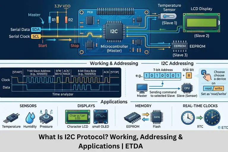
Learn what I2C protocol is, how I2C communication works, addressing, START and STOP conditions, ACK/NACK, registers, applications, and debugging. Embedded Tech Development Academy (ETDA).
- What Is I2C Protocol? Working, Addressing & Applications | ETDA
-
What Is I2C Protocol? Working, Addressing & Applications
- What Is I2C Protocol?
- I2C SDA and SCL Lines
- I2C Addressing
- ACK and NACK in I2C
- I2C STOP Condition
- I2C Read and Write Operations
- I2C Communication Speeds
- I2C Multi-Device Communication
- I2C Clock Stretching
- I2C Registers in Microcontrollers
- I2C Interrupts
- I2C Applications
- I2C vs SPI vs UART
- I2C Programming in Embedded C
- Common I2C Problems and Debugging
- How to Learn I2C Protocol
- Learn I2C and Embedded Systems at ETDA
-
Assured Placement Support at ETDA
- Placement Preparation
- FAQs
- What is I2C protocol?
- What are the two wires used in I2C?
- How does I2C addressing work?
- What is ACK in I2C?
- What is the difference between ACK and NACK?
- Why are pull-up resistors required in I2C?
- What is the difference between I2C and SPI?
- What is a repeated START condition?
- Where is I2C commonly used?
- Does ETDA provide placement support?
- Conclusion
What Is I2C Protocol? Working, Addressing & Applications
I2C, or Inter-Integrated Circuit, is a synchronous serial communication protocol widely used in embedded systems to connect microcontrollers with sensors, memory devices, RTCs, displays, ADCs, DACs, and other integrated circuits. One of its biggest advantages is that multiple devices can communicate over the same two primary signal lines.
Unlike UART, which normally uses separate transmit and receive lines, I2C uses a shared two-wire bus consisting of SDA (Serial Data) and SCL (Serial Clock).
For engineering students searching for a Top Embedded Training Institute in Bangalore, understanding I2C is an important part of learning embedded communication protocols. Embedded Tech Development Academy (ETDA) provides practical training in Embedded C, ARM microcontrollers, UART, SPI, I2C, CAN, RTOS, and embedded Linux, along with assured placement support.
What Is I2C Protocol?
I2C stands for Inter-Integrated Circuit. It is a synchronous, serial, multi-device communication protocol originally developed by Philips Semiconductor.
I2C allows a controller to communicate with one or more peripheral devices using two main wires:
- SDA — Serial Data
- SCL — Serial Clock
The clock signal synchronizes data transfer between devices.
Main Features of I2C
I2C provides several useful features for embedded applications:
- Two primary communication lines
- Device addressing
- Multi-device communication
- Acknowledgement mechanism
- Synchronous data transfer
- Support for read and write operations
- Relatively low pin count
- Open-drain/open-collector signaling
Why I2C Is Popular
A major advantage of I2C is that several peripherals can share the same SDA and SCL lines.
For example, a single microcontroller can communicate with:
- Temperature sensor
- EEPROM
- RTC
- OLED display
- Accelerometer
using the same two bus lines, provided the devices have appropriate addresses and electrical configuration.
Basic I2C Connection
A simplified I2C bus looks like:
Microcontroller → SDA → Multiple I2C Devices
Microcontroller → SCL → Multiple I2C Devices
All devices also share a common electrical reference.
I2C SDA and SCL Lines
Understanding the two I2C signals is fundamental.
SDA – Serial Data
SDA carries the actual data transferred between the controller and peripheral.
It is a bidirectional line.
Data can travel:
Controller → Peripheral
or:
Peripheral → Controller
SCL – Serial Clock
SCL carries the clock generated by the controller during a typical transaction.
The clock determines when data should be sampled and transferred.
Open-Drain Signaling
I2C devices generally use open-drain or open-collector outputs.
Devices pull the bus LOW when required, while pull-up resistors allow the bus to return HIGH.
Pull-Up Resistors
External pull-up resistors are normally required on SDA and SCL.
Their value depends on factors such as:
- Bus capacitance
- Operating voltage
- Clock frequency
- Number of connected devices
- Rise-time requirements
Incorrect pull-up selection can cause slow signal rise times or unreliable communication.
How I2C Communication Works
I2C communication uses defined bus conditions and a structured transaction.
A typical transaction can be represented as:
START → Address → R/W Bit → ACK → Data → ACK → STOP
START Condition
A START condition indicates the beginning of an I2C transaction.
When the bus is idle, SDA and SCL are normally HIGH. A START occurs when SDA transitions from HIGH to LOW while SCL remains HIGH.
Address Transmission
After START, the controller sends the address of the intended peripheral.
The address allows multiple devices to share the same bus.
Read/Write Bit
The transaction includes a read/write indication.
Typically:
- 0 = Write
- 1 = Read
The exact interpretation follows the I2C transaction format implemented by the controller hardware.
I2C Addressing
Addressing is one of the most important features of I2C.
7-Bit Addressing
Many I2C devices use 7-bit addresses.
The address identifies a particular peripheral on the bus.
For example:
The controller uses the address to select the appropriate device.
10-Bit Addressing
I2C also defines 10-bit addressing for applications requiring a larger address space.
However, many common sensors and peripheral ICs use 7-bit addressing.
Address Conflicts
Two devices with the same fixed I2C address can create a conflict if they are connected directly to the same bus.
Solutions can include:
- Changing a configurable address
- Using an I2C multiplexer
- Using separate I2C buses
- Using a device-specific enable or selection mechanism
ACK and NACK in I2C
I2C uses acknowledgement to indicate whether a transferred byte was accepted.
ACK – Acknowledge
After a byte is transmitted, the receiving device can generate an ACK.
An ACK tells the transmitter that the receiver successfully recognized the byte and is ready for the next part of the transaction.
NACK – Not Acknowledge
A NACK indicates that the receiver did not acknowledge the byte or that the transaction is intentionally ending.
NACK During Read
During a read operation, the controller can use NACK to indicate that it does not want another byte, followed by a STOP condition.
I2C STOP Condition
A STOP condition indicates the end of a transaction.
STOP Sequence
A STOP condition occurs when SDA transitions from LOW to HIGH while SCL is HIGH.
The bus then returns to its idle state.
START and STOP Importance
START and STOP conditions allow devices to identify transaction boundaries.
Repeated START
I2C also supports a Repeated START condition.
It allows the controller to begin another transaction without first releasing the bus with a STOP condition.
This is particularly useful when a controller first writes a register address and then reads data from the same device.
I2C Read and Write Operations
I2C supports both write and read transactions.
I2C Write Operation
A typical write sequence may be:
START → Address + Write → ACK → Register Address → ACK → Data → ACK → STOP
For example, a microcontroller may write a configuration value into a sensor register.
Typical Use
Writing is commonly used to:
- Configure sensors
- Set operating modes
- Write EEPROM data
- Configure displays
- Change device settings
I2C Read Operation
A typical register read may involve:
START → Address + Write → ACK → Register Address → ACK → Repeated START → Address + Read → ACK → Data → NACK → STOP
Why Repeated START Is Useful
Many I2C sensors use an internal register pointer.
The controller first specifies which register it wants to read and then changes the transaction direction to receive the data.
Multi-Byte Reads
A controller can often read multiple bytes in a single transaction, acknowledging each byte until the final byte.
I2C Communication Speeds
I2C defines multiple operating speed categories.
Standard Mode
Standard Mode supports communication up to 100 kbit/s.
Fast Mode
Fast Mode supports communication up to 400 kbit/s.
Fast Mode Plus
Fast Mode Plus can support speeds up to 1 Mbit/s under the appropriate electrical conditions.
High-Speed Mode
High-Speed Mode supports higher communication rates, up to 3.4 Mbit/s, when the hardware and system meet the required specifications.
Choosing the Speed
The appropriate speed depends on:
- Peripheral capability
- Bus capacitance
- Pull-up resistor values
- PCB layout
- Cable length
- Required data rate
Always check the peripheral datasheet before selecting an operating speed.
I2C Multi-Device Communication
One of I2C’s major strengths is its ability to connect multiple devices to the same bus.
Shared Bus
Multiple peripherals can share:
- SDA
- SCL
Each device is identified by its address.
Example System
A microcontroller could communicate with:
| Device | Example Function |
|---|---|
| Temperature sensor | Temperature measurement |
| EEPROM | Non-volatile storage |
| RTC | Time and date |
| Accelerometer | Motion sensing |
| OLED | Display |
All can potentially use the same SDA and SCL bus.
Bus Management
The controller must ensure that transactions are correctly addressed and that the bus is not improperly held by a malfunctioning device.
I2C Clock Stretching
Clock stretching is an important I2C feature.
What Is Clock Stretching?
A peripheral can temporarily hold SCL LOW to delay the continuation of communication.
This gives the peripheral additional time to process data.
Why Clock Stretching Is Used
A slower peripheral may need extra processing time before it can continue the transaction.
Hardware Compatibility
Not every controller implementation handles every clock-stretching scenario identically, so developers should verify hardware support when selecting an I2C controller and peripheral combination.
I2C Registers in Microcontrollers
I2C peripherals are controlled through hardware registers.
Common Register Functions
Depending on the microcontroller, I2C registers may configure:
- Clock speed
- Device address
- Data transmission
- Data reception
- START condition
- STOP condition
- ACK/NACK
- Interrupts
- Status flags
Status Registers
Status information may indicate:
- Bus busy
- START detected
- Address acknowledged
- Data transmitted
- Data received
- Arbitration lost
- Bus error
Register-Level Programming
Understanding these registers helps embedded engineers troubleshoot communication problems at the hardware level rather than relying only on high-level libraries.
I2C Interrupts
I2C communication can be implemented using polling or interrupts.
Polling
In polling-based communication, firmware repeatedly checks status flags.
A simplified concept is:
Limitations
The CPU remains occupied while waiting for the operation to complete.
I2C Applications
I2C is widely used in embedded electronics.
Sensors
Common I2C peripherals include:
- Temperature sensors
- Humidity sensors
- Pressure sensors
- Accelerometers
- Gyroscopes
- Magnetometers
EEPROM
I2C EEPROMs can store:
- Configuration values
- Calibration parameters
- Device information
- User settings
Real-Time Clock
RTC devices use I2C to exchange time and date information with a microcontroller.
Displays
Small OLED and LCD controllers can use I2C to reduce the number of required GPIO connections.
Power Management
Some power-management ICs use I2C for configuration and monitoring.
I2C vs SPI vs UART
Choosing a communication protocol depends on system requirements.
| Feature | I2C | SPI | UART |
|---|---|---|---|
| Clock | Synchronous | Synchronous | Asynchronous |
| Main Signal Lines | SDA, SCL | MOSI, MISO, SCLK, CS | TX, RX |
| Addressing | Yes | Usually via CS | Usually no |
| Multiple Devices | Yes | Yes | Limited |
| Full Duplex | Generally no | Yes | Typically yes |
| Wiring | Low | Higher | Low |
| Common Use | Sensors, ICs | Fast peripherals | Modules, debugging |
When Should You Choose I2C?
I2C is a strong choice when:
- Several peripherals need to share a bus
- GPIO availability is limited
- Moderate data rates are sufficient
- Devices support I2C addressing
When SPI Is Better
SPI may be preferred when higher throughput or full-duplex communication is important.
When UART Is Better
UART is often preferred for simple point-to-point communication, debugging interfaces, GPS modules, Bluetooth modules, and serial modems.
I2C Programming in Embedded C
Embedded C developers commonly configure I2C through peripheral registers or hardware abstraction libraries.
Typical I2C Initialization
Firmware generally performs steps such as:
- Enable I2C peripheral clock.
- Configure SDA and SCL pins.
- Configure pull-up circuitry.
- Set I2C clock speed.
- Enable the I2C peripheral.
- Configure interrupts if required.
- Implement START and STOP handling.
- Implement read/write functions.
Simplified I2C Write
i2c_start();
i2c_send_address(DEVICE_ADDR, WRITE);
i2c_send_byte(REG_ADDR);
i2c_send_byte(DATA);
i2c_stop();
Simplified I2C Read
i2c_start();
i2c_send_address(DEVICE_ADDR, WRITE);
i2c_send_byte(REG_ADDR);
i2c_start();
i2c_send_address(DEVICE_ADDR, READ);
data = i2c_read();
i2c_stop();
The exact implementation depends on the microcontroller and I2C peripheral.
Common I2C Problems and Debugging
I2C communication can fail because of software configuration, electrical issues, or incorrect device addressing.
Wrong Device Address
A common problem is using the wrong address.
Developers should check whether the datasheet provides:
- 7-bit address
- 8-bit address format
- Configurable address pins
Missing Pull-Ups
Without suitable pull-up resistors, SDA and SCL may not return HIGH correctly.
Incorrect Clock Speed
Operating faster than the peripheral supports can result in unreliable communication.
Bus Stuck LOW
A device that holds SDA or SCL LOW can prevent normal communication.
A logic analyzer or oscilloscope can help identify:
- START condition
- Device address
- ACK/NACK
- Data bytes
- STOP condition
- Clock timing
How to Learn I2C Protocol
A structured learning path helps engineers understand I2C at both software and hardware levels.
Step 1: Learn C and Embedded C
Focus on:
- Functions
- Pointers
- Structures
- Bitwise operations
- Volatile variables
Step 2: Learn Digital Electronics
Understand:
- Logic levels
- Pull-up resistors
- Open-drain outputs
- Binary data
Step 3: Understand I2C Timing
Study:
- START
- STOP
- ACK
- NACK
- Addressing
- Clock stretching
Step 4: Program a Microcontroller
Implement:
- I2C initialization
- Device detection
- Register write
- Register read
- Multi-byte transfer
Step 5: Build Projects
Useful projects include:
- I2C temperature sensor
- RTC interface
- EEPROM interface
- OLED display
- Accelerometer interface
- Environmental monitoring system
Learn I2C and Embedded Systems at ETDA
Embedded Tech Development Academy (ETDA) provides practical embedded systems training designed to help engineering students develop industry-relevant hardware and firmware skills.
Technical Areas Covered
Training can include:
- C Programming
- Embedded C
- C++
- Data Structures
- ARM Cortex-M
- STM32
- LPC1768
- GPIO
- Timers
- ADC
- PWM
- UART
- SPI
- I2C
- CAN
- Ethernet
- RTOS
- Embedded Linux
- Internet of Things (IoT)
Hands-On Learning
Students can work with microcontrollers and real peripherals to understand I2C addressing, register configuration, timing, sensor communication, debugging, and driver development.
Assured Placement Support at ETDA
Embedded Tech Development Academy (ETDA) combines technical training with career preparation through assured placement support.
Placement Preparation
Students can receive support in:
- Resume preparation
- Technical interview preparation
- Embedded C coding
- Communication protocol interview questions
- Aptitude preparation
- Mock interviews
- HR interview preparation
- Communication skills
- Career guidance
Industry-Oriented Skills
Hands-on projects allow students to explain real hardware-software interactions during technical interviews and demonstrate practical knowledge of embedded communication protocols.
FAQs
What is I2C protocol?
I2C, or Inter-Integrated Circuit, is a synchronous serial communication protocol that allows microcontrollers to communicate with multiple peripheral devices using SDA and SCL lines.
What are the two wires used in I2C?
The two primary I2C signals are SDA (Serial Data) and SCL (Serial Clock).
How does I2C addressing work?
The controller sends the address of the intended peripheral at the beginning of a transaction. Many I2C devices use 7-bit addresses, although 10-bit addressing is also defined.
What is ACK in I2C?
ACK stands for Acknowledge. It indicates that the receiving device has accepted a transmitted byte and is ready for the next part of the transaction.
What is the difference between ACK and NACK?
ACK indicates successful acknowledgement of a byte. NACK indicates that the byte was not acknowledged or that the receiving side is intentionally ending the transfer.
Why are pull-up resistors required in I2C?
I2C uses open-drain/open-collector signaling, so pull-up resistors allow SDA and SCL to return to the HIGH state when no device is actively pulling them LOW.
What is the difference between I2C and SPI?
I2C uses two primary signal lines and supports device addressing, making it convenient for multiple peripherals. SPI generally offers higher throughput and full-duplex communication but requires additional signal lines, particularly chip-select signals.
What is a repeated START condition?
A repeated START allows a controller to begin another transaction without first generating a STOP condition. It is commonly used when writing a register address and then reading data from the same peripheral.
Where is I2C commonly used?
I2C is widely used for temperature sensors, EEPROMs, RTCs, accelerometers, gyroscopes, OLED displays, ADCs, DACs, and power-management devices.
Does ETDA provide placement support?
Yes. Embedded Tech Development Academy (ETDA) provides assured placement support, including technical interview preparation, resume guidance, coding practice, aptitude training, mock interviews, and career guidance for students preparing for embedded technology careers.
Conclusion
I2C is one of the most important communication protocols for embedded systems because it allows multiple peripherals to communicate with a microcontroller using only two primary signal lines. Its addressing mechanism, acknowledgement system, synchronous clocking, and multi-device capability make it particularly useful for sensors, EEPROMs, RTCs, displays, and other integrated circuits.
A strong understanding of I2C requires more than knowing SDA and SCL. Embedded engineers should understand START and STOP conditions, 7-bit and 10-bit addressing, ACK/NACK, read and write transactions, repeated START, clock stretching, pull-up resistors, bus timing, interrupts, registers, and debugging techniques.
For engineering students searching for a Top Embedded Training Institute in Bangalore, Embedded Tech Development Academy (ETDA) provides practical training in C, Embedded C, ARM microcontrollers, UART, SPI, I2C, CAN, RTOS, Embedded Linux, and Internet of Things (IoT). With hands-on projects and assured placement support, Embedded Tech Development Academy (ETDA) helps learners develop the technical foundation needed for embedded software and firmware careers.
Author: ETDA Trainers
Experience: 10+ Years of Industry Experience in Embedded Systems, IoT, and Embedded C Programming