
8051 Microcontroller Interrupts: Types, Vector Addresses & ISR
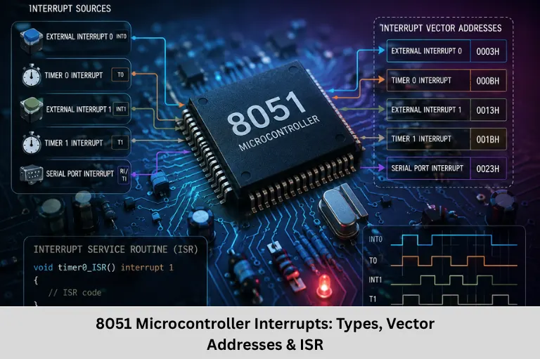
Learn 8051 interrupts, interrupt types, IE and IP registers, vector addresses, ISR execution, Timer 0 interrupt programming, priority, and applications.
- 8051 Microcontroller Interrupts: Types, Vector Addresses & ISR
-
Understanding Interrupts in the 8051 Microcontroller
- What Is an Interrupt in 8051?
- Types of Interrupts in the 8051
- Interrupt Enable Register
- Interrupt Priority Register
- How 8051 Interrupt Handling Works
- Timer 0 Interrupt Programming Example
- Interrupts and Real-Time Embedded Systems
- Interrupt Applications in 8051
- Interrupt Design Best Practices
- Frequently Asked Questions
- Conclusion
Understanding Interrupts in the 8051 Microcontroller
An interrupt is a hardware or software mechanism that temporarily changes the normal execution flow of a microcontroller program to handle an event that requires immediate attention. Interrupts are fundamental to real-time embedded systems because they allow the CPU to respond to important events without continuously checking peripheral status through polling.
The 8051 microcontroller provides a simple but powerful interrupt architecture that makes it possible to handle external events, timer overflows, and serial communication efficiently. A typical 8051-based application may need to monitor an external switch, generate periodic timing events, receive serial data, or count external pulses while simultaneously executing its main application. Interrupts allow these activities to be handled asynchronously.
The standard 8051 architecture provides five interrupt sources: External Interrupt 0, Timer 0 overflow, External Interrupt 1, Timer 1 overflow, and the serial port interrupt. Derivative 8051 devices may provide additional interrupt sources, such as Timer 2 and other peripheral interrupts, so the exact interrupt architecture depends on the particular 8051 family member.
For engineers learning 8051 microcontroller programming, Embedded C, assembly language, interrupt service routines, timer programming, real-time embedded systems, and peripheral interfacing, interrupt handling is an essential technical concept.
Embedded Tech Development Academy (ETDA) focuses on practical embedded systems training covering microcontrollers, Embedded C, assembly programming, communication protocols, timers, interrupts, and firmware development. As a Top Embedded Training Institute in Bangalore, Embedded Tech Development Academy (ETDA) emphasizes hands-on technical learning along with assured placement support.
For students who want to develop practical firmware-development skills, learning 8051 interrupts at Embedded Tech Development Academy (ETDA), a Top Embedded Training Institute in Bangalore, can provide a strong foundation in event-driven programming, real-time processing, and microcontroller peripherals with assured placement support.
What Is an Interrupt in 8051?
An interrupt is a request that causes the 8051 CPU to temporarily suspend its current program and execute an Interrupt Service Routine (ISR).
Polling vs Interrupts
In polling, the CPU repeatedly checks whether an event has occurred.
For example:
Check Timer Flag
      ↓
Check Timer Flag
      ↓
Check Timer Flag
      ↓
Process Event
This consumes CPU time even when no event is present.
With interrupts:
Main Program
     ↓
Interrupt Occurs
     ↓
Execute ISR
     ↓
Return to Main Program
The CPU can perform other operations until the interrupt condition occurs.
Why Interrupts Are Important
Interrupts are useful for:
- Real-time event handling
- Timer-based operations
- External hardware events
- Serial communication
- Pulse counting
- Periodic control tasks
Types of Interrupts in the 8051
The classic 8051 provides five interrupt sources
Standard 8051 Interrupt Sources
| Interrupt Source | Trigger/Event | Vector Address |
|---|---|---|
| External INT0 | External interrupt request | 0003H |
| Timer 0 | Timer 0 overflow | 000BH |
| External INT1 | External interrupt request | 0013H |
| Timer 1 | Timer 1 overflow | 001BH |
| Serial Port | RI or TI condition | 0023H |
External Interrupts
INT0 is available on P3.2, while INT1 is available on P3.3 in the standard 8051 pin configuration.
Depending on the configuration of the IT0 and IT1 bits in the TCON register, external interrupts can operate using edge-triggered or level-triggered operation.
Timer Interrupts
Timer 0 and Timer 1 can generate interrupts when their timer/counter registers overflow.
The corresponding flags are:
TF0— Timer 0 overflow flagTF1— Timer 1 overflow flag
Serial Interrupt
The serial port uses a combined interrupt request. The two important flags are:
RI— Receive interrupt flagTI— Transmit interrupt flag
Software normally determines which condition caused the serial interrupt and clears the appropriate flag as required.
Interrupt Enable Register
The Interrupt Enable (IE) register determines which interrupts are enabled.
IE Register Structure
For the classic 8051:
| Bit | Name | Function |
|---|---|---|
| IE.7 | EA | Global interrupt enable |
| IE.4 | ES | Serial interrupt enable |
| IE.3 | ET1 | Timer 1 interrupt enable |
| IE.2 | EX1 | External INT1 enable |
| IE.1 | ET0 | Timer 0 interrupt enable |
| IE.0 | EX0 | External INT0 enable |
Some 8051 derivatives add additional interrupt-enable bits.
Global Interrupt Enable
The EA bit acts as the global interrupt enable.
SETB EAenables maskable interrupts globally.
An individual interrupt must also be enabled using its corresponding bit.
For example:
SETB ET0enables Timer 0 interrupts.
Interrupt Priority Register
The Interrupt Priority (IP) register determines whether supported interrupt sources operate at low or high priority.
Priority Configuration
For the classic 8051, the relevant bits include:
| Bit | Name | Interrupt |
|---|---|---|
| IP.4 | PS | Serial |
| IP.3 | PT1 | Timer 1 |
| IP.2 | PX1 | INT1 |
| IP.1 | PT0 | Timer 0 |
| IP.0 | PX0 | INT0 |
A bit value of 0 normally selects low priority, while 1 selects high priority.
Why Interrupt Priority Matters
If two interrupt requests occur, priority determines which interrupt can be serviced first. A high-priority interrupt can interrupt a currently executing low-priority ISR, subject to the 8051 interrupt architecture.
Proper priority assignment is important when some events have stricter timing requirements than others.
How 8051 Interrupt Handling Works
The basic interrupt sequence is:
Step 1 — Interrupt Request
A hardware event occurs, such as Timer 0 overflowing.
Step 2 — Interrupt Conditions Are Checked
The 8051 checks the relevant interrupt-enable and global-enable conditions.
Step 3 — Program Counter Is Saved
When an interrupt is accepted, the CPU saves the return address on the stack.
Step 4 — ISR Execution
Execution transfers to the interrupt vector associated with the interrupt.
Step 5 — Return Using RETI
The ISR ends with:
RETIRETI indicates that the interrupt service routine has completed and allows the processor to resume normal program execution.
Timer 0 Interrupt Programming Example
The following example demonstrates a basic Timer 0 interrupt using 8051 assembly language.
Timer 0 ISR Example
ORG 0000H
LJMP MAIN

ORG 000BH
LJMP TIMER0_ISR

MAIN:
    MOV TMOD, #01H
    MOV TH0, #0FCH
    MOV TL0, #018H

    SETB ET0
    SETB EA
    SETB TR0

MAIN_LOOP:
    SJMP MAIN_LOOP

TIMER0_ISR:
    CLR TF0
    MOV TH0, #0FCH
    MOV TL0, #018H

    RETI

END
Code Explanation
TMOD = 01H configures Timer 0 in Mode 1, which is a 16-bit timer mode.
TH0 and TL0 contain the initial timer value.
ET0 enables the Timer 0 interrupt.
EA enables maskable interrupts globally.
TR0 starts Timer 0.
When Timer 0 overflows, the processor transfers control to the Timer 0 vector at 000BH, where execution branches to TIMER0_ISR.
Reloading the Timer
The timer is reloaded inside the ISR so that another overflow can occur after the desired interval. The exact interval depends on the oscillator frequency, 8051 clock-divider architecture, timer mode, and reload value.
Interrupts and Real-Time Embedded Systems
Interrupts are essential when an embedded system must respond to events within predictable timing requirements.
External Event Handling
External interrupts can be used for:
- Push buttons
- Digital sensors
- Emergency signals
- Pulse detection
- Hardware status signals
Timer-Based Tasks
Timer interrupts can generate periodic events for:
- LED blinking
- Software timers
- Sampling
- Motor-control scheduling
- Time-base generation
Serial Communication
The serial interrupt allows the processor to respond when a byte is received or transmission-related conditions occur without constantly polling the serial flags.
Interrupt Applications in 8051
Keypad and Input Systems
External interrupts can be used when a hardware event requires immediate processing.
Pulse and Frequency Measurement
External events can trigger interrupts for pulse counting and timing measurements.
Industrial Control
Timer interrupts can support periodic control operations in automation systems.
Communication Systems
The serial interrupt provides an event-driven method for UART communication.
Interrupt Design Best Practices
Keep ISRs Short
An ISR should perform only the time-critical work required to service the event.
Avoid lengthy loops and unnecessary processing inside an ISR.
Protect Shared Data
If the main program and ISR access the same variables, developers should carefully consider atomicity and data consistency.
Understand Flag Handling
Some interrupt flags are cleared automatically under particular conditions, while others require software handling. Developers should consult the specific 8051 device documentation.
Avoid Excessive Work in an ISR
A good architecture is:
Interrupt
   ↓
Capture Event
   ↓
Set Flag / Store Data
   ↓
RETI
   ↓
Main Program Processes Event
This minimizes interrupt latency and keeps the firmware responsive.
Frequently Asked Questions
How many interrupts does the standard 8051 have?
The classic 8051 has five interrupt sources: External INT0, Timer 0 overflow, External INT1, Timer 1 overflow, and the serial port interrupt. Some 8051 derivatives provide additional interrupt sources.
What is the interrupt vector address of Timer 0 in 8051?
The Timer 0 interrupt vector address in the standard 8051 is 000BH.
What is the function of the IE register?
The Interrupt Enable (IE) register controls the global and individual enabling of maskable interrupts. The EA bit provides global interrupt control, while bits such as ET0, ET1, EX0, EX1, and ES enable specific interrupt sources.
What is the purpose of RETI in 8051?
RETI, or Return from Interrupt, terminates an interrupt service routine and returns program execution to the point where the interrupted program was suspended. It also informs the interrupt system that interrupt servicing has completed.
What is the difference between polling and interrupts?
In polling, the CPU repeatedly checks a peripheral or hardware flag to determine whether an event has occurred. With interrupts, the hardware requests CPU attention when an event occurs, allowing the CPU to perform other work until the event requires servicing.
Conclusion
Interrupts are one of the most important features of the 8051 microcontroller architecture because they allow firmware to respond to asynchronous hardware and peripheral events without continuously polling every status flag. The classic 8051 provides five standard interrupt sources: INT0, Timer 0, INT1, Timer 1, and the serial port, each associated with a predefined interrupt vector address.
To implement interrupts correctly, an embedded developer must understand the IE register, EA bit, individual interrupt-enable bits, IP register, interrupt priority, interrupt flags, vector addresses, stack operation, ISR execution, and the RETI instruction. Timer interrupts additionally require knowledge of timer modes, reload values, oscillator frequency, and timer overflow behavior.
Interrupts are widely used in 8051 Embedded C programming, real-time systems, UART communication, timer applications, pulse measurement, industrial automation, keypad interfaces, and hardware event processing. Proper ISR design is critical: routines should be short, deterministic where practical, and careful when accessing data shared with the main program.
Embedded Tech Development Academy (ETDA) provides practical training in 8051 microcontrollers, Embedded C, assembly programming, timers, interrupts, communication protocols, and firmware development. As a Top Embedded Training Institute in Bangalore, Embedded Tech Development Academy (ETDA) focuses on hands-on technical learning and provides assured placement support for career-focused learners.
For engineers developing their embedded programming skills, Embedded Tech Development Academy (ETDA), a Top Embedded Training Institute in Bangalore, can provide practical exposure to interrupt-driven firmware and microcontroller programming together with assured placement support. Mastering 8051 interrupt architecture provides a strong foundation for understanding interrupt controllers and real-time event handling in more advanced microcontroller families.
Author: ETDA Trainers
Experience: 10+ Years of Industry Experience in Embedded Systems, IoT, and Embedded C Programming