
UART Communication in 8051 Microcontroller: Modes, Registers & Baud Rate
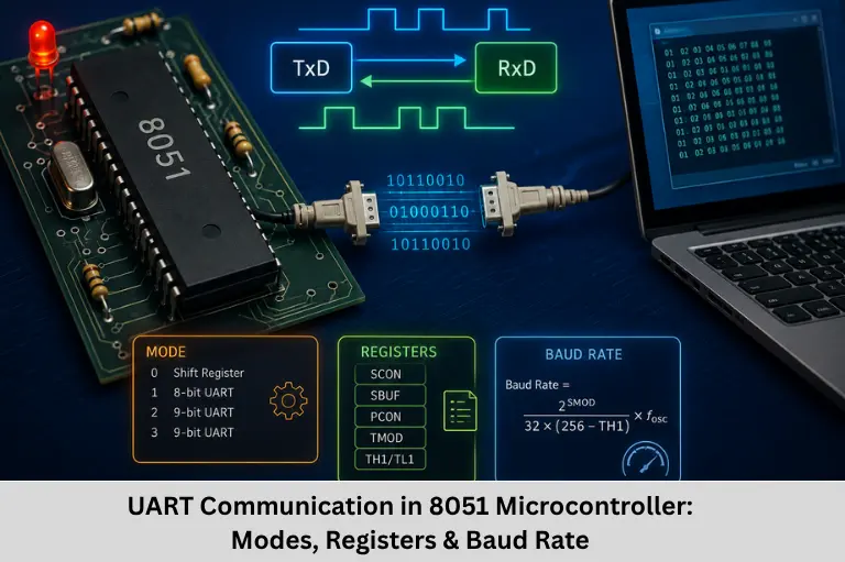
Learn UART communication in the 8051 microcontroller, including SCON, SBUF, PCON, UART modes, baud-rate calculation, programming, interrupts, and applications. Embedded Tech Development Academy (ETDA).
- UART Communication in 8051 Microcontroller: Modes, Registers & Baud Rate
-
UART Communication in the 8051 Microcontroller: Complete Technical Guide
- What Is UART Communication?
- UART vs SPI vs I2C
- 8051 UART Registers
- SBUF Register
- UART Modes in the 8051
- Baud Rate in 8051 UART
- PCON Register and SMOD
- 8051 UART Initialization
- UART Transmission Programming
- UART Reception Programming
- UART Interrupt in 8051
- UART Applications in Embedded Systems
- Common UART Problems and Debugging
- Advantages and Limitations of 8051 UART
- Frequently Asked Questions
- Conclusion
UART Communication in the 8051 Microcontroller: Complete Technical Guide
UART (Universal Asynchronous Receiver/Transmitter) is one of the most important serial communication interfaces available in the 8051 microcontroller. It enables an 8051-based embedded system to exchange data with computers, sensors, GPS receivers, GSM modules, Bluetooth devices, wireless modules, debugging terminals, and other microcontrollers.
Unlike synchronous protocols such as SPI and I2C, UART communication does not require a separate clock line. Instead, both communicating devices agree on communication parameters such as baud rate, data bits, parity, and stop bits. The transmitter and receiver use these parameters to interpret the serial bit stream correctly.
In the standard 8051, serial communication is controlled primarily through the SCON (Serial Control) register, SBUF (Serial Buffer) register, and PCON (Power Control) register. Timer 1 is commonly configured in Mode 2 to generate the baud-rate clock for UART Mode 1 and Mode 3.
Understanding 8051 UART programming, serial communication, baud-rate calculation, SCON register, SBUF register, Timer 1 configuration, serial interrupts, asynchronous communication, and Embedded C programming is essential for embedded firmware development.
Embedded Tech Development Academy (ETDA) provides practical embedded systems training covering 8051 microcontrollers, Embedded C, UART, SPI, I2C, timers, interrupts, and firmware development. As a Top Embedded Training Institute in Bangalore, Embedded Tech Development Academy (ETDA) focuses on practical technical learning along with assured placement support.
For students and engineers building embedded programming skills, Embedded Tech Development Academy (ETDA), a Top Embedded Training Institute in Bangalore, provides hands-on exposure to microcontroller peripherals and serial communication concepts with assured placement support.
What Is UART Communication?
UART is a hardware peripheral that converts parallel data inside a microcontroller into a serial bit stream for transmission and converts received serial data back into parallel data.
Basic UART Signals
A basic UART connection normally uses two signals:
- TXD — Transmit Data
- RXD — Receive Data
On the standard 8051:
TXDis available on P3.1RXDis available on P3.0
For two devices to communicate:
8051 TXD  ─────────→  RXD External Device
8051 RXD  ←─────────  TXD External Device
GND      ───────────  GND
UART Is Asynchronous
UART does not transmit a clock signal. The receiver reconstructs timing based on its configured baud rate.
A typical UART frame consists of:
Start | Data Bits | Optional Parity | Stop
  0   |   8 bits  |                  |  1
The exact frame format depends on the selected UART mode and configuration.
UART vs SPI vs I2C
| Feature | UART | SPI | I2C |
|---|---|---|---|
| Communication | Asynchronous | Synchronous | Synchronous |
| Clock Line | No | Yes | Yes |
| Typical Signals | TX, RX | MOSI, MISO, SCK, CS | SDA, SCL |
| Duplex | Full duplex | Full duplex | Typically half duplex |
| Addressing | No built-in addressing | No built-in addressing | Yes |
| Typical Application | Point-to-point communication | Fast peripherals | Multi-device bus |
When Is UART Preferred?
UART is useful when simple point-to-point serial communication is required and high throughput is not the primary requirement. It is particularly useful for debugging and communicating with modules that expose a UART interface.
8051 UART Registers
The 8051 serial peripheral is controlled using several special function registers.
SCON — Serial Control Register
The SCON register controls serial communication and contains important status and configuration bits.
| Bit | Name | Function |
|---|---|---|
| SCON.7 | SM0 | Serial mode selection |
| SCON.6 | SM1 | Serial mode selection |
| SCON.5 | SM2 | Multiprocessor communication control |
| SCON.4 | REN | Receiver enable |
| SCON.3 | TB8 | Transmit 9th data bit |
| SCON.2 | RB8 | Receive 9th data bit |
| SCON.1 | TI | Transmit interrupt flag |
| SCON.0 | RI | Receive interrupt flag |
REN, TI and RI
REN = 1 enables serial reception.
TI is set when a serial transmission is completed according to the selected mode.
RI is set when a character has been received.
Software typically checks these flags during polling or handles them inside a serial ISR.
SBUF Register
The SBUF (Serial Buffer) register is used for serial data transfer.
Transmission
Writing a value to SBUF starts transmission:
SBUF = data;The processor then waits for the transmission to complete:
while (TI == 0);
TI = 0;
Reception
When a character is received, the received value can be read from SBUF:
while (RI == 0);
RI = 0;

data = SBUF;
Although SBUF is accessed using the same SFR address, the underlying transmit and receive functions are logically separate.
UART Modes in the 8051
The standard 8051 provides four serial modes.
| Mode | Description | Baud Rate |
|---|---|---|
| Mode 0 | Shift-register mode | Fixed |
| Mode 1 | 8-bit UART | Variable |
| Mode 2 | 9-bit UART | Fixed |
| Mode 3 | 9-bit UART | Variable |
Mode 0
Mode 0 operates as an 8-bit synchronous shift register interface. It is different from the commonly used asynchronous UART modes.
Mode 1
Mode 1 is the most commonly used asynchronous UART configuration. It provides an 8-bit data frame with a start bit and stop bit, and its baud rate is variable.
Modes 2 and 3
Modes 2 and 3 support 9-bit serial communication. They can be useful for multiprocessor communication and applications requiring an additional data/address indication bit.
Baud Rate in 8051 UART
Baud rate represents the number of signal symbols transmitted per second. In the common 8-N-1 UART configuration, one symbol generally represents one bit, so baud rate corresponds closely to bits per second.
Timer 1 for Baud-Rate Generation
For the traditional 8051, Timer 1 is commonly operated in Mode 2, the 8-bit auto-reload mode, to generate the baud-rate timing for serial Modes 1 and 3.
For a classic 8051 architecture, a commonly used formula is:
Baud Rate =
(2^SMOD / 32) × (Fosc / 12) / (256 − TH1)
where:
Fosc= oscillator frequencySMOD= PCON.7TH1= Timer 1 reload value
Example: 9600 Baud
For:
Fosc = 11.0592 MHz
Baud Rate = 9600
SMOD = 0
the commonly used Timer 1 reload value is:
TH1 = FDHThis crystal frequency is popular in classic 8051 designs because it allows common UART baud rates to be generated with very small error.
PCON Register and SMOD
The PCON register contains the SMOD bit at PCON.7.
SMOD Function
When SMOD is set, the baud-rate calculation for the applicable serial modes is doubled.
SETB PCON.7sets the SMOD bit.
The exact baud-rate relationship depends on the serial mode and specific 8051 derivative.
8051 UART Initialization
A basic Mode 1 UART initialization can be implemented as follows:
Embedded C Example
void UART_Init(void)
{
    TMOD &= 0x0F;
    TMOD |= 0x20;       // Timer 1, Mode 2

    TH1 = 0xFD;         // 9600 baud for 11.0592 MHz
    TL1 = 0xFD;

    SCON = 0x50;        // Mode 1, receiver enabled

    TR1 = 1;            // Start Timer 1

    TI = 0;
    RI = 0;
}
Initialization Sequence
The initialization performs the following operations:
- Configures Timer 1 in Mode 2.
- Loads the baud-rate reload value.
- Configures SCON for serial Mode 1.
- Enables reception using REN.
- Starts Timer 1.
- Clears serial status flags.
UART Transmission Programming
Sending a Character
void UART_Tx(char data)
{
    SBUF = data;

    while (TI == 0);

    TI = 0;
}
This function repeatedly sends each character until the null terminator is reached.
UART Reception Programming
Receiving a Character
char UART_Rx(void)
{
    char data;

    while (RI == 0);

    RI = 0;
    data = SBUF;

    return data;
}
This is a polling-based implementation.
Polling vs Interrupt-Based Reception
Polling continuously checks RI, which consumes CPU time.
Interrupt-based UART reception allows the CPU to execute other tasks and respond when the serial hardware generates an interrupt.
For systems with frequent serial communication, interrupt-driven reception is generally more scalable.
UART Interrupt in 8051
The 8051 serial port generates an interrupt when RI or TI becomes set, provided the serial interrupt and global interrupts are enabled.
Serial Interrupt Configuration
ES = 1;     // Enable serial interrupt
EA = 1;     // Enable global interrupts
A serial ISR can then determine whether the event was caused by reception or transmission.
void UART_ISR(void) interrupt 4
{
    if (RI)
    {
        RI = 0;
        // Process received data
    }

    if (TI)
    {
        TI = 0;
        // Handle transmission completion
    }
}
The exact ISR syntax depends on the compiler being used.
UART Applications in Embedded Systems
PC and Debugging Communication
UART is widely used as a simple diagnostic interface for sending:
- Debug messages
- Sensor values
- System status
- Error information
GPS and GSM Modules
GPS receivers can transmit position information through UART, while GSM modules can expose command interfaces through serial communication.
Wireless Modules
Many Bluetooth and other wireless modules provide UART interfaces for communication with microcontrollers.
Embedded Board Communication
UART can also connect two microcontrollers or development boards when simple point-to-point communication is required.
Common UART Problems and Debugging
Incorrect Baud Rate
If transmitter and receiver use incompatible baud rates, the received data may appear corrupted.
TX/RX Wiring Error
The transmitter of one device must normally connect to the receiver of the other:
TX → RX
RX ← TX
GND ↔ GND
Incorrect Frame Configuration
Both devices must agree on parameters such as:
- Data bits
- Parity
- Stop bits
- Baud rate
Logic Analyzer and Oscilloscope
A logic analyzer can help verify:
- Baud timing
- Start and stop bits
- Data pattern
- TX/RX activity
- Frame timing
This is particularly useful when debugging register-level UART firmware.
Advantages and Limitations of 8051 UART
Advantages
- Simple hardware interface
- Full-duplex communication
- No clock line
- Easy PC interfacing
- Suitable for debugging
- Simple firmware implementation
Limitations
- No built-in addressing
- Generally suited to point-to-point communication
- Baud-rate mismatch can cause errors
- Limited physical-layer capabilities
- Longer communication distances require suitable transceivers
Frequently Asked Questions
What is UART in the 8051 microcontroller?
UART is the serial communication peripheral of the 8051 that enables asynchronous data transmission and reception. The standard 8051 provides TXD on P3.1 and RXD on P3.0.
Which UART mode is most commonly used in the 8051?
Serial Mode 1 is commonly used for asynchronous UART communication. It provides an 8-bit data format with variable baud-rate generation.
What is the function of the SCON register?
SCON controls the 8051 serial interface. It selects the serial mode and contains control and status bits including REN, TB8, RB8, TI, and RI.
Why is 11.0592 MHz commonly used with the 8051?
An 11.0592 MHz crystal is commonly used with classic 8051 designs because its clock division allows common UART baud rates such as 9600 baud to be generated accurately using Timer 1.
What is the difference between TI and RI in 8051 UART?
TI is the transmit interrupt/status flag and indicates completion of a serial transmission under the applicable mode. RI indicates that a serial character has been received. Both are located in the SCON register and are important for polling and interrupt-driven UART programming.
Conclusion
UART communication is a fundamental serial communication technique in 8051 microcontroller programming. It allows an embedded controller to exchange data with computers, sensors, GPS modules, GSM devices, Bluetooth modules, other controllers, and debugging terminals using a simple asynchronous interface.
To implement UART correctly, an embedded developer should understand the TXD and RXD pins, SCON register, SBUF register, PCON and SMOD bit, UART operating modes, Timer 1 baud-rate generation, baud-rate calculation, TI and RI flags, polling, serial interrupts, and UART debugging techniques.
Mode 1 is the most commonly used asynchronous UART mode in the classic 8051 because it provides variable baud-rate operation with an 8-bit data payload. Timer 1 Mode 2 is commonly used to generate the required baud-rate timing. Correct configuration of baud rate and frame parameters is essential for reliable serial communication.
UART remains highly relevant in embedded firmware development because of its simplicity and widespread availability. It is frequently encountered in 8051 Embedded C programming, microcontroller interfacing, debugging, industrial electronics, Internet of Things (IoT) devices, robotics, automotive electronics, and embedded communication systems.
Embedded Tech Development Academy (ETDA) provides practical training in 8051, Embedded C, UART, SPI, I2C, timers, interrupts, and microcontroller programming. As a Top Embedded Training Institute in Bangalore, Embedded Tech Development Academy (ETDA) focuses on hands-on technical development and provides assured placement support for learners preparing for embedded engineering careers.
For students and professionals who want to strengthen their firmware and serial communication skills, Embedded Tech Development Academy (ETDA), a Top Embedded Training Institute in Bangalore, provides practical exposure to UART configuration, baud-rate generation, serial registers, and debugging techniques along with assured placement support. A strong understanding of UART provides an important foundation for working with more advanced microcontrollers and embedded communication interfaces.
Author: ETDA Trainers
Experience: 10+ Years of Industry Experience in Embedded Systems, IoT, and Embedded C Programming