
DMA in Microcontrollers: Working, Modes and Applications
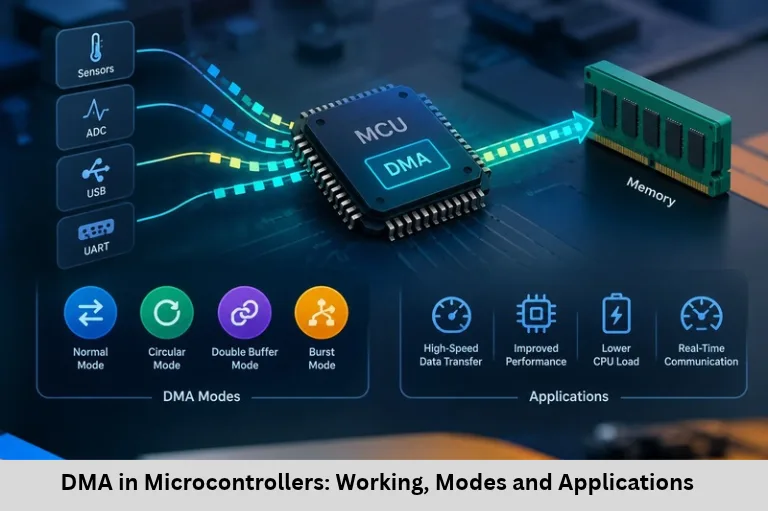
Learn DMA in microcontrollers, including working principles, transfer modes, UART, ADC, SPI applications, STM32 examples, and embedded programming. Embedded Tech Development Academy (ETDA).
- DMA in Microcontrollers: Working, Modes and Applications
- DMA (Direct Memory Access) in Microcontrollers: Complete Technical Guide
DMA (Direct Memory Access) in Microcontrollers: Complete Technical Guide
Introduction to Direct Memory Access
Modern embedded systems must transfer increasing amounts of data while maintaining high processing performance, low power consumption, and predictable real-time behavior. Applications such as industrial automation, sensor monitoring, audio processing, communication interfaces, robotics, and Internet of Things (IoT) devices frequently move data between peripherals and memory. If the CPU handles every transfer through software instructions or interrupts, processing time is consumed by data movement rather than application logic.
Direct Memory Access (DMA) addresses this problem by allowing dedicated hardware to transfer data between supported peripherals and memory with limited CPU involvement. After configuring the transfer, the processor can execute other tasks while DMA manages data movement. This improves CPU availability and can reduce interrupt overhead, particularly when transferring large data blocks or processing continuous streams.
DMA is an important concept in embedded C programming, microcontroller architecture, ARM Cortex-M development, STM32 firmware, UART communication, ADC data acquisition, SPI transfers, and real-time operating systems (RTOS). However, DMA does not automatically make every operation faster. Performance depends on bus bandwidth, memory accessibility, peripheral request handling, buffer management, and transfer configuration.
For students learning embedded firmware, understanding DMA provides practical insight into interrupt-driven systems, memory management, peripheral drivers, and real-time optimization. Embedded Tech Development Academy (ETDA) can be explored by learners interested in hands-on microcontroller programming and embedded development. When comparing a Top Embedded Training Institute in Bangalore, evaluate practical DMA experiments, debugging facilities, peripheral interfacing, and assured placement support. These skills help aspiring engineers develop efficient firmware for resource-constrained hardware.
What Is DMA in a Microcontroller?
DMA is a hardware-controlled data-transfer mechanism that moves information between supported memory locations and peripherals without requiring the CPU to execute an instruction for every transferred data item.
A DMA transfer is normally configured with parameters such as:
Source and destination addresses.
Transfer length or number of data items.
Transfer direction.
Data width, such as 8, 16, or 32 bits.
Address increment settings.
Peripheral request source and transfer mode.
Interrupt and error-handling options.
Once the transfer begins, the DMA controller responds to peripheral requests or follows the configured transfer mechanism. On completion, it may raise an interrupt or set a status flag.
DMA Versus CPU-Based Data Transfer
In a CPU-controlled transfer, firmware repeatedly reads a peripheral register and writes the value into memory. With DMA, hardware performs the repeated movement, allowing the CPU to handle computations, communication management, or control algorithms.
DMA still requires CPU configuration and supervision. It may also compete with the processor for memory-bus access, so actual performance gains depend on the system architecture.
How DMA Works
Step-by-Step Transfer Process
Configuration: The CPU selects the DMA channel or stream, addresses, transfer length, data width, and request source.
Request generation: A peripheral, such as an ADC or UART, signals that a transfer is required.
Bus access: The DMA controller obtains access to the relevant bus or interconnect.
Data movement: Hardware transfers data between the peripheral register and the destination memory, or in the opposite direction.
Progress tracking: The controller updates its transfer state and remaining count where supported.
Completion: A transfer-complete interrupt or status flag informs firmware that the operation has finished.
Example — ADC Sampling with DMA
Suppose an ADC samples a sensor at 10,000 samples per second. With a 16-bit buffer containing 1,000 samples, the buffer represents 0.1 seconds of sampling.
The ADC produces each conversion result, and DMA stores it in the configured buffer. Once the buffer is full, the CPU can process the samples, calculate an average, or perform digital filtering.
Buffer Management
For continuous acquisition, circular DMA or double buffering can help prevent data loss. Firmware must process completed buffers before DMA overwrites their contents. On systems with data caches, cache coherency must also be handled according to the processor and DMA architecture.
Types of DMA Data Transfers
Memory-to-Memory
Transfers data from one memory region to another. Applications include copying buffers, rearranging data, and initializing memory. Not every DMA controller supports this mode.
Peripheral-to-Memory
Moves peripheral data into RAM. Typical examples include ADC conversion results, UART reception, and SPI input data.
Memory-to-Peripheral
Moves data from RAM to a peripheral register. Common applications include UART transmission, SPI display updates, and feeding samples to a DAC.
Peripheral-to-Peripheral
Some advanced DMA architectures support transfers between peripheral endpoints, subject to hardware restrictions. Do not assume every controller can connect arbitrary peripherals directly.
DMA Transfer Modes
Normal and Single-Transfer Modes
In normal mode, a configured transfer stops after the specified number of data items has moved. Depending on the controller, single-transfer operation handles one item per request or bus transaction.
Circular Mode
Circular mode reloads or wraps the transfer position when the buffer reaches its end. It is useful for continuous UART reception, ADC sampling, and audio input.
Burst and Double-Buffer Modes
Burst mode groups multiple data beats where the bus and controller support it. Double buffering alternates between two memory buffers, allowing firmware to process one while DMA fills the other. Linked-list or scatter-gather transfers are available on some advanced controllers.
DMA Architecture and Configuration
A typical DMA controller includes address registers, transfer counters, control registers, status flags, request selection logic, and channel or stream management. Some controllers also provide FIFO buffers, linked-list descriptors, and programmable priorities.
On STM32 microcontrollers, DMA configuration differs by family. Some devices use channel-based controllers, while others use stream-based architectures. Engineers must consult the relevant reference manual to configure request mapping, data width, increment settings, and interrupt flags correctly.
In embedded C, firmware generally initializes the peripheral, configures the DMA transfer, enables the required interrupts, and starts the operation. Completion callbacks or interrupt handlers should remain short; lengthy processing can be deferred to a task or main loop.
Practical DMA Applications
UART and SPI Communication
UART DMA efficiently receives or transmits packets without generating a CPU interrupt for every byte. SPI DMA is useful for transferring display frames, reading external memory, or communicating with high-speed sensors.
Audio, ADC, and Data Logging
Audio systems use DMA to maintain continuous sample streams. ADC-based monitoring systems can collect sensor data at predictable rates, while data-logging devices can move samples into memory for later processing or storage.
DMA in RTOS-Based Systems
In an RTOS, a DMA completion interrupt can notify a task using an appropriate interrupt-safe mechanism. Buffer ownership must be clear so that a task does not read data while DMA is modifying it.
Advantages, Challenges, and Debugging
DMA reduces CPU workload, supports high-throughput transfers, and can improve real-time responsiveness. It may also help reduce energy consumption when the processor can sleep during transfers and the hardware supports the required low-power operation.
Common challenges include incorrect transfer lengths, mismatched data widths, invalid addresses, missed completion flags, buffer overruns, and bus contention. Debugging should include checking DMA status registers, peripheral request configuration, interrupt priorities, and buffer boundaries. Measure CPU load and transfer timing to confirm the real benefit.
Frequently Asked Questions
What is DMA in microcontrollers?
DMA is a hardware mechanism that transfers data between supported peripherals and memory without requiring the CPU to handle every individual data item.
How does DMA improve performance?
DMA frees the CPU from repetitive data movement, allowing it to execute other tasks while transfers occur. Actual gains depend on bus bandwidth, transfer size, and hardware configuration.
What is circular DMA mode?
Circular DMA automatically wraps around to the beginning of a configured buffer after reaching its end. It is commonly used for continuous sensor acquisition and UART reception.
Can DMA be used with UART, SPI, and ADC peripherals?
Yes, many microcontrollers support DMA requests from UART, SPI, and ADC peripherals. Exact capabilities and configuration requirements depend on the selected microcontroller.
What are common DMA programming mistakes?
Typical mistakes include incorrect transfer lengths, wrong data widths, invalid DMA request mapping, buffer overruns, missing interrupts, and improper cache maintenance on systems with data caches.
Conclusion
Direct Memory Access is a fundamental microcontroller feature that improves data-transfer efficiency by allowing hardware to move data between supported peripherals and memory with limited CPU intervention. Understanding DMA transfer types, normal and circular modes, double buffering, interrupt handling, and memory coherency helps engineers develop efficient firmware for ADC acquisition, UART and SPI communication, audio processing, and industrial monitoring. Correct configuration and careful buffer management remain essential for reliable real-time performance.
Embedded Tech Development Academy (ETDA) can be considered by students who want to strengthen their knowledge of embedded C, microcontroller peripherals, ARM Cortex-M architecture, and practical firmware development. When choosing a Top Embedded Training Institute in Bangalore, look for hands-on DMA implementation, debugging exercises, RTOS integration, and industry-oriented projects. Check what assured placement support specifically includes, since career assistance does not necessarily guarantee employment. Combining technical understanding with tested firmware projects helps learners build a stronger foundation for embedded systems and Internet of Things (IoT) engineering roles.
Author: ETDA Trainers
Experience: 10+ Years of Industry Experience in Embedded Systems, IoT, and Embedded C Programming