
Ultra-Low-Latency ISR Pipelines: Design & Optimization
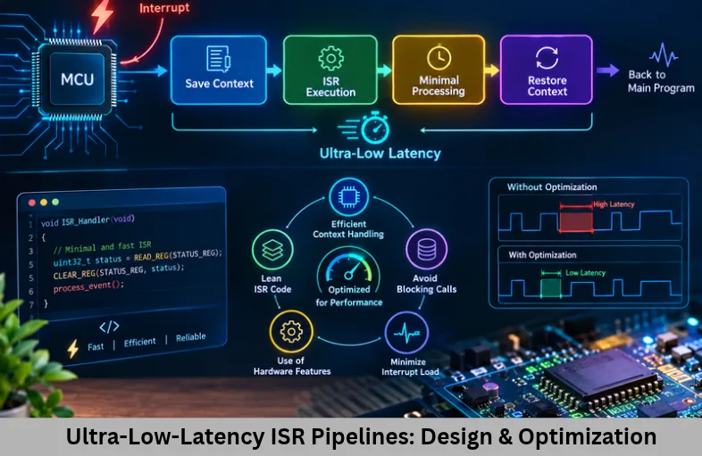
Learn ultra-low-latency ISR pipeline design, interrupt priorities, DMA, Cortex-M tail-chaining, zero-copy buffers, jitter analysis, and real-time debugging. Embedded Tech Development Academy (ETDA).
- Ultra-Low-Latency ISR Pipelines: Design & Optimization
-
Creating Ultra-Low-Latency ISR Pipelines: A Comprehensive Technical Guide
- Introduction
- Understanding ISR Latency
- Architectural Techniques for Low-Latency ISRs
- Optimize Memory, DMA, and Data Transfer
- Processor-Specific ISR Optimization
- Real-World ISR Pipeline Designs
- Measuring and Debugging Interrupt Performance
- Ultra-Low-Latency ISR Checklist
- Frequently Asked Questions
- Conclusion
Creating Ultra-Low-Latency ISR Pipelines: A Comprehensive Technical Guide
Introduction
Interrupt Service Routines (ISRs) are essential components of real-time embedded systems because they allow a processor to respond to hardware events without continuously polling peripherals. In applications such as industrial servo drives, motor controllers, sensor-fusion systems, RF communication devices, robotics, and high-speed data acquisition, even a small delay can affect control accuracy and system reliability. Designing ultra-low-latency ISR pipelines therefore requires careful coordination between processor architecture, interrupt handling, memory access, DMA transfers, and real-time scheduling.
Important concepts include interrupt latency optimization, worst-case execution time (WCET), interrupt jitter reduction, Cortex-M exception handling, RTOS interrupt priorities, tightly coupled memory (TCM), and zero-copy data transfer. Engineers must also understand bus contention, cache misses, critical sections, interrupt masking, and deferred processing to achieve predictable response times. Rather than optimizing only the ISR instructions, developers must analyze the complete path from a hardware event to the required system response.
For aspiring embedded engineers, Embedded Tech Development Academy (ETDA) provides a relevant learning context for exploring microcontroller programming, RTOS concepts, and real-time firmware development. Learners searching for a Top Embedded Training Institute in Bangalore should prioritize hands-on work with timers, DMA, interrupt controllers, and debugging tools. Structured practice and assured placement support can complement technical learning and help candidates prepare for embedded development roles.
Understanding ISR Latency
ISR latency is the time between an interrupt event and the beginning of the corresponding handler. Total response time extends further, until the system completes the required action.
Main Components of Interrupt Response Time
Peripheral latency: Delay between the physical event and interrupt generation.
Interrupt-controller latency: Time required to recognize and prioritize the pending interrupt.
CPU entry latency: Time spent completing the current instruction, performing exception entry, saving required context, and fetching the vector.
Handler latency: Delay caused by software wrappers, higher-priority handlers, and instructions executed before the essential operation.
Response latency: Total time until the required output or control action occurs.
Sources of Unpredictable Delay
Interrupt masking, long critical sections, flash wait states, bus contention, and higher-priority interrupts can increase latency. Cache misses and translation lookaside buffer (TLB) misses may also affect systems with application-class processors and virtual-memory support.
Define a Measurable Latency Budget
Specify the maximum acceptable response time for each interrupt. Separate entry latency, ISR execution time, and deferred processing time. This makes performance requirements measurable instead of relying on average execution time alone.
Architectural Techniques for Low-Latency ISRs
Configure Interrupt Priorities Correctly
Assign high priority to genuinely time-critical events, such as PWM synchronization or precise timer capture. Avoid assigning the highest priority to every interrupt, because this can starve lower-priority activities.
In FreeRTOS, interrupts above the configured configMAX_SYSCALL_INTERRUPT_PRIORITY threshold on Cortex-M require special care: they generally must not call RTOS APIs that are restricted by that threshold. Verify the processor’s priority numbering and the port-specific configuration before setting priorities.
Use the Top-Half and Bottom-Half Pattern
The top half performs only the immediate work necessary to acknowledge or capture the event. It may read a hardware status register, capture a timestamp, store a sample, or notify a deferred handler.
The bottom half performs longer operations in a task or another suitable deferred context. Filtering sensor data, calculating control algorithms, formatting logs, and processing packets usually belong outside the time-critical ISR.
Reduce Unnecessary Instructions and Calls
Avoid printf(), blocking operations, dynamic memory allocation, lengthy loops, and complex library calls inside latency-sensitive handlers. Use direct register access only when supported and necessary, and use static inline functions when they genuinely improve generated code.
Inlining is not automatically faster: it may increase code size or instruction-cache pressure. Inspect compiler output and measure the result on the target device.
Optimize Memory, DMA, and Data Transfer
Place Critical Code in Deterministic Memory
On supported microcontrollers, placing critical handlers in tightly coupled memory (TCM) or suitable SRAM can reduce instruction-fetch delays compared with flash memory that introduces wait states. Actual performance depends on the device, memory configuration, and bus architecture.
For application-class processors, instruction-cache locking or cache preloading may be available, but these features are architecture-specific. Cache coherency and memory barriers must be handled correctly when multiple cores or DMA engines access shared data.
Implement Zero-Copy Ring Buffers
Instead of copying each sample through multiple queues, an ISR can place data into a preallocated ring buffer and signal a consumer task. This reduces copying and allocation overhead.
Protect Buffer Ownership
For a single-producer, single-consumer ring buffer, use appropriate atomic operations or a verified synchronization design. volatile alone does not guarantee thread safety or memory ordering. Define how buffer overflow, wraparound, and producer-consumer synchronization are handled.
Use DMA for High-Rate Sampling
For ADC acquisition, a typical pipeline is:
ADC → DMA → Ring Buffer → Minimal ISR → Processing Task
DMA transfers blocks of samples without requiring an interrupt for every sample. Interrupts can be generated on buffer completion or half-buffer completion, reducing CPU overhead while preserving timely processing.
Processor-Specific ISR Optimization
Cortex-M Tail-Chaining
Cortex-M processors support tail-chaining, which can reduce exception-transition overhead when another eligible interrupt is pending as an ISR completes. Instead of performing a complete exception return followed by a new entry sequence, the processor can transition directly to the next handler.
The actual benefit depends on the core, interrupt priorities, and execution conditions. Keep handlers short enough to allow predictable scheduling of subsequent events.
Minimize Stack and Context-Saving Costs
Reduce deep call chains, large local variables, and unnecessary register usage in critical handlers. Floating-point operations can introduce additional context-saving costs on processors with floating-point hardware, depending on configuration and lazy-stacking behavior.
Control Shared-Bus Contention
DMA, graphics engines, other processor cores, and flash controllers may compete for memory or interconnect bandwidth. Where possible, use suitable memory placement, DMA priorities, and bus configurations to limit interference with time-critical execution.
Real-World ISR Pipeline Designs
Motor Control Loop
For a fast field-oriented control (FOC) system, a timer synchronizes PWM events and ADC sampling. DMA transfers current measurements into a buffer, and a minimal ISR records completion or signals the control task. The control algorithm must still finish before the next deadline; deferring work does not eliminate its execution-time requirement.
RF Timing and Input Processing
An RF timing handler may capture a timer value and update hardware scheduling registers before returning. For game-controller or user-input interrupts, the ISR can record the event while debouncing and higher-level processing run later.
These designs prioritize predictable response, bounded execution, and minimal interference with unrelated tasks.
Measuring and Debugging Interrupt Performance
Use Hardware-Based Timing Measurements
Useful tools include the Cortex-M DWT cycle counter (CYCCNT) where available, ITM/ETM trace, GPIO toggles measured with an oscilloscope or logic analyzer, and RTOS tracing tools.
Measure interrupt entry time, ISR execution duration, worst-case latency, and jitter under realistic load. Test with DMA traffic and concurrent tasks active, not only under idle conditions.
Validate Worst-Case Behavior
Repeat measurements across relevant operating conditions, including cache cold starts where applicable, maximum communication traffic, and bursts of simultaneous interrupts. Record the maximum observed latency and retain sufficient margin against the deadline. A measured maximum is not necessarily a formal WCET bound, so safety-critical systems may require additional analysis.
Ultra-Low-Latency ISR Checklist
Set priorities according to real deadlines.
Keep critical handlers short and bounded.
Avoid blocking calls and dynamic allocation in the ISR.
Use DMA and preallocated buffers for high-rate data.
Verify synchronization and memory ordering.
Check interrupt masking and shared-bus contention.
Measure worst-case latency and jitter on the target hardware.
Practical training in interrupt-driven programming, DMA, and RTOS scheduling can help learners understand these design trade-offs. Embedded Tech Development Academy (ETDA) is relevant to students building these embedded development skills. Those comparing a Top Embedded Training Institute in Bangalore should check for practical microcontroller labs, real-time debugging exercises, and project-based evaluation. Assured placement support can further complement technical preparation.
Frequently Asked Questions
What is ISR latency?
ISR latency is the time between an interrupt event being generated and the corresponding interrupt handler beginning execution. Total response time also includes the processing needed to complete the required action.
How can interrupt latency be reduced?
Use appropriate interrupt priorities, minimize interrupt masking, keep handlers short, optimize memory access, reduce bus contention, and measure performance on the actual hardware.
What is the top-half and bottom-half ISR approach?
The top half performs urgent, bounded work inside the ISR. The bottom half handles longer processing later in a task, thread, or supported deferred-execution mechanism.
How does DMA improve ISR performance?
DMA transfers data between peripherals and memory with less CPU involvement. Interrupts can occur at buffer or transfer boundaries instead of for every sample, reducing interrupt frequency.
What is tail-chaining in Cortex-M processors?
Tail-chaining is an exception-handling optimization that lets a Cortex-M processor transition directly to another eligible pending interrupt without performing the full return-and-entry sequence between handlers.
Which tools are useful for measuring ISR latency?
Common options include the DWT cycle counter on supported Cortex-M cores, ITM/ETM trace, GPIO timing measurements, oscilloscopes, logic analyzers, and RTOS tracing tools.
Conclusion
Creating an ultra-low-latency ISR pipeline is a system-level engineering task, not simply a matter of reducing source-code instructions. Reliable results require understanding exception entry, interrupt priorities, processor pipelines, deterministic memory access, DMA operation, buffer synchronization, and the effects of shared resources. A carefully designed top-half/bottom-half architecture keeps immediate response work bounded while moving computationally intensive tasks into an appropriate deferred context.
Engineers should validate their designs using cycle counters, trace facilities, oscilloscopes, logic analyzers, and realistic worst-case workload tests. Monitoring WCET, jitter, and deadline margins helps distinguish a fast average response from a genuinely predictable real-time system. For learners pursuing these capabilities, Embedded Tech Development Academy (ETDA) offers a relevant direction for exploring embedded programming and real-time design. Choosing a Top Embedded Training Institute in Bangalore with practical hardware and firmware exercises can strengthen this foundation, while assured placement support may help candidates prepare for industry opportunities.
Author: ETDA Trainers
Experience: 10+ Years of Industry Experience in Embedded Systems, IoT, and Embedded C Programming