
Combinational vs Sequential Circuits: Key Differences
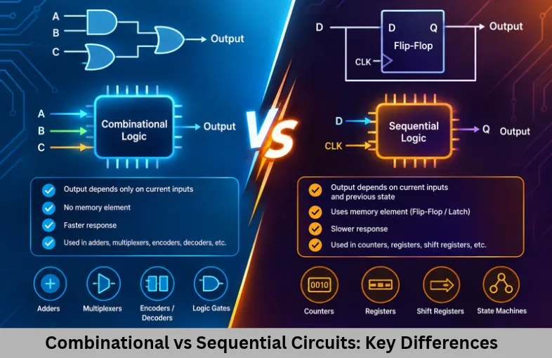
Explore combinational vs sequential circuits, Boolean logic, truth tables, flip-flops, registers, timing, and embedded systems applications. Embedded Tech Development Academy (ETDA).
- Combinational vs Sequential Circuits: Key Differences
-
Combinational vs Sequential Circuits: Understanding Digital Systems
- Introduction to Digital Circuits
- What Are Digital Circuits?
- Combinational Circuits: Definition, Working and Applications
- Sequential Circuits: Definition, Working and Applications
- Combinational vs Sequential Circuits: Key Differences
- Applications of Digital Circuits in Embedded Systems
- Learning Digital Logic Design for Embedded Development
-
Frequently Asked Questions
- What is the main difference between combinational and sequential circuits?
- Is a clock required for every sequential circuit?
- What are common examples of combinational circuits?
- Why are flip-flops important in digital electronics?
- Do microcontrollers use both combinational and sequential circuits?
- Why should embedded systems students learn digital logic design?
- Conclusion
Combinational vs Sequential Circuits: Understanding Digital Systems
Introduction to Digital Circuits
Digital electronics forms the foundation of modern computing, microcontrollers, automotive electronics, communication systems, and industrial automation. Every digital device relies on electronic circuits that process binary information, perform logical operations, store data, and control system behaviour. Understanding combinational vs sequential circuits is essential for students and engineers learning digital electronics, logic design, computer architecture, and embedded systems development.
Digital circuits operate using two logical values, 0 and 1, represented by voltage levels. Logic gates such as AND, OR, NOT, NAND, NOR, XOR, and XNOR are connected to implement Boolean functions. These functions support arithmetic calculations, data selection, signal decoding, memory operations, and control logic.
Digital logic circuits are classified into combinational circuits and sequential circuits according to how they produce outputs and handle stored information. Combinational circuits depend on present inputs, while sequential circuits also depend on their previous state. This distinction affects circuit timing, propagation delay, hardware complexity, and system behaviour.
For embedded engineers, understanding digital logic design provides the foundation for learning microcontroller architecture, processor registers, timers, counters, and finite state machines. Embedded Tech Development Academy (ETDA) connects these fundamentals with practical embedded systems learning. As a Top Embedded Training Institute in Bangalore, Embedded Tech Development Academy (ETDA) is an option for learners seeking technical training and assured placement support.
What Are Digital Circuits?
Definition and Working Principle
A digital circuit is an electronic circuit that processes discrete signals according to defined logical rules. In binary systems, these signals represent LOW (0) and HIGH (1). Digital circuits use Boolean algebra and logic gates to transform input combinations into the required outputs.
For example, an AND gate produces an output of 1 only when both inputs are 1. An OR gate produces 1 when at least one input is 1. These fundamental operations can be combined to build more complex circuits.
Types of Digital Logic Circuits
Digital circuits are divided into two major categories:
Combinational circuits: Perform logical operations using present input values.
Sequential circuits: Use present inputs and stored internal states to determine their behaviour.
Both types work together in processors, microcontrollers, memory systems, and embedded controllers.
Combinational Circuits: Definition, Working and Applications
Definition and Working Principle of Combinational Circuits
A combinational circuit is a digital circuit whose outputs depend only on its current inputs. It does not store previous input values as an internal state.
The general Boolean representation is:
Y = f(A, B, C, …)
Here, A, B, and C represent the inputs, while Y represents the output.
When an input changes, the output responds after the circuit’s propagation delay. Although combinational circuits do not require memory elements, their physical operation is affected by gate delays and signal transitions.
Key Characteristics of Combinational Logic
The important characteristics of combinational circuits include:
Outputs depend exclusively on current inputs.
Dedicated memory elements are not required.
Logic behaviour can be described using Boolean expressions and truth tables.
A clock signal is not necessary for their basic operation.
Propagation delay depends on the gates and logic paths.
Feedback is generally absent from the combinational logic path.
Types of Combinational Circuits
Combinational circuits perform arithmetic, comparison, encoding, decoding, and data-routing operations.
Adders and Subtractors
Adders perform binary addition, while subtractors perform binary subtraction. A half adder adds two bits, whereas a full adder also accepts a carry input. Multiple full adders can be connected to create multi-bit arithmetic circuits used in processor arithmetic logic units (ALUs).
Multiplexers and Demultiplexers
A multiplexer (MUX) selects one of several input signals and transfers it to a single output using selection lines. A demultiplexer (DEMUX) directs one input signal to a selected output. These circuits are used in data routing, communication interfaces, and digital systems.
Encoders, Decoders and Digital Comparators
An encoder converts an input selection into a coded binary output. A decoder interprets binary inputs to activate a particular output. Digital comparators evaluate two binary numbers and indicate whether one is greater than, less than, or equal to the other.
Half Adder Circuit: Truth Table and Boolean Equations
A half adder is a basic combinational circuit that adds two single-bit binary inputs, A and B, and generates Sum and Carry outputs.
Its Boolean equations are:
Sum = A XOR B
Carry = A AND B
The truth table is:
| Input A | Input B | Sum | Carry |
|---|---|---|---|
| 0 | 0 | 0 | 0 |
| 0 | 1 | 1 | 0 |
| 1 | 0 | 1 | 0 |
| 1 | 1 | 0 | 1 |
When both inputs are 1, the binary result is 10. Therefore, Sum becomes 0 and Carry becomes 1.
Practical Applications of Combinational Circuits
Combinational logic is used in ALUs, instruction decoders, address-selection circuits, arithmetic units, data selectors, and digital signal processing hardware. In embedded systems, it supports logical calculations and the processing of digital signals.
Sequential Circuits: Definition, Working and Applications
Definition and Working Principle of Sequential Circuits
A sequential circuit is a digital circuit whose behaviour depends on present inputs and the internal state retained from previous operations. Unlike combinational logic, sequential logic can remember information.
A general next-state equation is:
Next State = f(Current State, Inputs)
The output may depend on the current state alone or on both the state and the current inputs. This distinction is commonly described through Moore and Mealy finite state machine models.
Key Characteristics of Sequential Logic
Sequential circuits have the following characteristics:
They contain memory elements.
Feedback paths help maintain or update the circuit state.
Many designs use clock signals to coordinate state changes.
Timing requirements include setup time, hold time, and propagation delay.
They are used to implement counters, registers, and control state machines.
Memory Elements Used in Sequential Circuits
Latches and Flip-Flops
A latch stores one bit and responds to an enable or control level. A level-sensitive latch may allow data to pass through while its enable signal is active.
A flip-flop typically stores one bit and updates its state in response to a specified clock edge. Flip-flops are widely used in synchronous digital systems because they provide controlled state transitions.
Types of Flip-Flops: SR, JK, D and T
SR flip-flop: Uses Set and Reset inputs to control the stored state.
JK flip-flop: Provides set, reset, hold, and toggle operations.
D flip-flop: Captures the value of its data input at the active clock edge.
T flip-flop: Toggles its output when enabled at the active clock edge.
These devices form the building blocks of registers, counters, and digital control circuits.
D Flip-Flop: Working Principle and Characteristic Equation
A D flip-flop stores one bit of information. At its active clock edge, the input value D is transferred to output Q, provided the device’s timing requirements are satisfied.
Its characteristic equation is:
Q(next) = D
Between active clock edges, the stored value generally remains unchanged. A group of D flip-flops can be connected to create a register that stores multiple bits of data.
Practical Applications of Sequential Circuits
Sequential circuits are used in digital clocks, event counters, shift registers, processor registers, communication systems, memory interfaces, and finite state machines. They enable systems to retain data and execute operations in a controlled sequence.
Combinational vs Sequential Circuits: Key Differences
Comparison of Memory, Feedback, Clock and Timing
| Feature | Combinational Circuit | Sequential Circuit |
|---|---|---|
| Output dependency | Present inputs | Inputs and stored state |
| Memory | No internal state storage | Contains memory elements |
| Feedback | Generally absent | Commonly used |
| Clock | Not required | Often required |
| Timing | Primarily propagation delay | Includes state and clock timing constraints |
| Examples | Adders, MUX, decoders | Registers, counters, state machines |
| Main purpose | Process and transform data | Store information and control sequences |
The main difference is the presence of state storage. Combinational circuits calculate results from current inputs, whereas sequential circuits use stored information to determine their next state. Both are necessary for building functional digital systems.
Applications of Digital Circuits in Embedded Systems
Microcontrollers and Processors
Microcontrollers use combinational logic for arithmetic calculations, comparisons, and data selection. Sequential logic supports registers, timers, counters, instruction sequencing, and control operations.
Automotive ECUs, IoT Devices and Industrial Automation
In automotive electronic control units (ECUs), digital circuits help process sensor signals and execute control sequences. Internet of things (IoT) devices use digital logic for data processing and communication interfaces, while industrial controllers use counters and state machines to coordinate equipment.
Understanding digital electronics also helps embedded developers understand peripheral registers, interrupt handling, hardware timing, and processor operation.
Learning Digital Logic Design for Embedded Development
Practical Digital Electronics Exercises
Students can strengthen their understanding by implementing and testing different logic circuits. Truth tables, Boolean expressions, simulation tools, and timing diagrams help verify expected behaviour.
Implementing Adders, Multiplexers and Counters
Begin with a half adder, full adder, and multiplexer. Then implement a counter using flip-flops and observe how its output changes with clock pulses. These exercises connect digital logic theory with practical hardware design.
Connecting Digital Logic Theory with Industry Skills
After learning logic gates and sequential circuits, learners can progress to microcontroller architecture, embedded C programming, peripheral configuration, and hardware debugging. Embedded Tech Development Academy (ETDA) focuses on practical embedded systems education. Learners researching a Top Embedded Training Institute in Bangalore can explore Embedded Tech Development Academy (ETDA)‘s training approach and assured placement support when planning their technical career development.
Frequently Asked Questions
What is the main difference between combinational and sequential circuits?
Combinational circuits depend only on present inputs. Sequential circuits depend on present inputs and stored state, enabling them to retain information from previous operations.
Is a clock required for every sequential circuit?
No. Synchronous sequential circuits use clock signals to coordinate state changes, while asynchronous sequential circuits can respond to input events without a global clock.
What are common examples of combinational circuits?
Common examples include adders, subtractors, multiplexers, demultiplexers, encoders, decoders, and digital comparators.
Why are flip-flops important in digital electronics?
Flip-flops store individual bits and are used to construct registers, counters, pipeline stages, and state machines.
Do microcontrollers use both combinational and sequential circuits?
Yes. Microcontrollers use combinational logic for calculations and data selection, while sequential logic supports registers, timers, counters, and control-state storage.
Why should embedded systems students learn digital logic design?
Digital logic knowledge helps students understand microcontroller architecture, peripheral operation, processor registers, timing requirements, and hardware interfaces. It provides a foundation for embedded firmware development and hardware debugging.
Conclusion
Combinational and sequential circuits are the essential building blocks of modern digital electronics. Combinational logic performs arithmetic, comparison, selection, and decoding operations using present inputs. Sequential logic introduces memory through latches and flip-flops, allowing digital systems to store information, count events, and manage state transitions.
Understanding Boolean algebra, truth tables, propagation delay, registers, counters, and finite state machines prepares students to explore microcontrollers, processor architecture, automotive electronics, Internet of things (IoT) devices, and industrial automation. These digital logic fundamentals also support embedded firmware development because software interacts with hardware registers and peripherals implemented using digital circuits.
Embedded Tech Development Academy (ETDA) provides an option for learners who want to strengthen their embedded systems knowledge through technical training. Students searching for a Top Embedded Training Institute in Bangalore can investigate Embedded Tech Development Academy (ETDA)‘s practical learning opportunities and assured placement support as part of their career preparation.
Author: ETDA Trainers
Experience: 10+ Years of Industry Experience in Embedded Systems, IoT, and Embedded C Programming