
7-Segment Display Interfacing with 8051
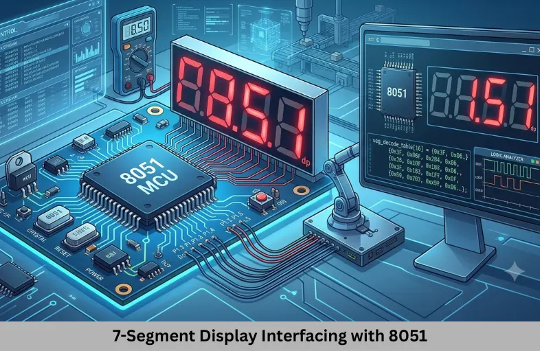
Learn 7-segment display interfacing with 8051 microcontroller using Embedded C, circuit connections, display codes, and practical examples. Embedded Tech Development Academy (ETDA).
- 7-Segment Display Interfacing with 8051
-
7-Segment Display Interfacing with 8051 Microcontroller
- What Is a 7-Segment Display?
- Components Required for 8051 Display Interfacing
- Circuit Connections for 7-Segment Display with 8051
- Embedded C Program for 8051 7-Segment Display
- Applications of 8051 Seven-Segment Display Interfacing
- Learn Embedded C and Microcontroller Interfacing at ETDA
-
Frequently Asked Questions
- What is a 7-segment display in embedded systems?
- How does an 8051 control a 7-segment display?
- What is the difference between common-anode and common-cathode displays?
- Which port is commonly used for 7-segment interfacing with 8051?
- Can an 8051 display numbers from 0 to 9?
- What is the purpose of resistors in a 7-segment display circuit?
- Conclusion
7-Segment Display Interfacing with 8051 Microcontroller
A 7-segment display is one of the most commonly used output devices in embedded systems. It is widely used in digital clocks, calculators, counters, electronic meters, temperature indicators, and industrial control panels. Interfacing a 7-segment display with an 8051 microcontroller is an excellent beginner project for understanding GPIO programming, digital output control, and Embedded C.
The 8051 microcontroller can control individual display segments through its I/O ports. By generating appropriate binary patterns, developers can display numbers from 0 to 9 and create simple counting applications. Students learning Embedded systems can use this project to understand hardware connections, current-limiting resistors, display coding, and firmware execution.
For students searching for a Top Embedded Training Institute in Bangalore, Embedded Tech Development Academy (ETDA) provides practical learning opportunities that help connect microcontroller theory with real hardware development, along with assured placement support.
What Is a 7-Segment Display?
A 7-segment display is an electronic display module consisting of seven LED segments arranged in a rectangular pattern. Each segment is identified using the letters A, B, C, D, E, F, and G. An additional decimal point, represented as DP, is available in many display modules.
By switching individual segments ON or OFF, the display can represent decimal digits and selected alphabetic characters. For example, displaying the digit 8 requires all seven segments to illuminate, whereas displaying 1 requires only segments B and C.
Segment Arrangement and Identification
The segments are arranged as follows:
A: Top horizontal segment
B: Upper-right vertical segment
C: Lower-right vertical segment
D: Bottom horizontal segment
E: Lower-left vertical segment
F: Upper-left vertical segment
G: Middle horizontal segment
The decimal point is positioned near the lower-right corner. Understanding this arrangement is essential because the firmware must activate the correct segments to display each digit.
Types of 7-Segment Displays
There are two common types of 7-segment displays: common anode and common cathode. In a common-anode display, all LED anodes are connected together, and a segment illuminates when its cathode is driven LOW.
In a common-cathode display, all LED cathodes are connected together, and a segment illuminates when its anode receives a HIGH signal. Therefore, the segment control logic differs between these two display types.
Common-Cathode Display Code
For a common-cathode display, the following hexadecimal patterns represent digits 0–9 when bit 0 controls segment A and bit 6 controls segment G.
| Digit | Hexadecimal Code |
|---|---|
| 0 | 0x3F |
| 1 | 0x06 |
| 2 | 0x5B |
| 3 | 0x4F |
| 4 | 0x66 |
| 5 | 0x6D |
| 6 | 0x7D |
| 7 | 0x07 |
| 8 | 0x7F |
| 9 | 0x6F |
These codes assume the decimal point is OFF and the segment connections follow the specified bit arrangement. Different wiring arrangements may require different display codes.
Components Required for 8051 Display Interfacing
The basic circuit requires an 8051 microcontroller, a single-digit 7-segment display, seven current-limiting resistors, a suitable power supply, and connecting wires. A development board can simplify power connections and provide convenient access to the microcontroller’s GPIO pins.
Current-limiting resistors are important because LEDs require controlled current to operate safely. The resistor value should be selected according to the LED forward voltage, supply voltage, and permitted segment current.
Circuit Connections for 7-Segment Display with 8051
In this example, Port 2 of the 8051 is used to control the seven segments. Each port pin is connected to a corresponding segment through a current-limiting resistor.
The connections are:
P2.0 → Segment A
P2.1 → Segment B
P2.2 → Segment C
P2.3 → Segment D
P2.4 → Segment E
P2.5 → Segment F
P2.6 → Segment G
The common cathode terminal of the display is connected to ground. P2.7 may be used for the decimal point if required, while keeping it LOW in this example.
For a practical circuit, verify the display pin configuration using its datasheet. Some display packages contain multiple common terminals, and these must be connected correctly for reliable operation.
Embedded C Program for 8051 7-Segment Display
The following program displays digits from 0 to 9 continuously using a common-cathode 7-segment display connected to Port 2.
Program Explanation
The program uses an array containing the hexadecimal codes for all ten decimal digits. The microcontroller sends each code to Port 2, causing the corresponding LED segments to illuminate.
A delay is introduced between successive digits so that the displayed numbers can be observed clearly. This approach is called lookup-table-based display programming.
Embedded C Code
#include <reg51.h>

unsigned char code seg_code[10] =
{
    0x3F, 0x06, 0x5B, 0x4F, 0x66,
    0x6D, 0x7D, 0x07, 0x7F, 0x6F
};

void delay(void)
{
    unsigned int i, j;

    for(i = 0; i < 500; i++)
        for(j = 0; j < 127; j++);
}

void main(void)
{
    unsigned char digit;

    while(1)
    {
        for(digit = 0; digit < 10; digit++)
        {
            P2 = seg_code[digit];
            delay();
        }
    }
}
Understanding Program Execution
The array stores the segment patterns required to display each decimal digit. The outer infinite loop ensures that the counting sequence repeats continuously, while the inner loop displays each digit sequentially.
The delay function uses nested loops to introduce a software delay. Its actual duration depends on the oscillator frequency, compiler optimization, and instruction execution time. For accurate timing applications, hardware timers are preferable to software delays.
Applications of 8051 Seven-Segment Display Interfacing
Interfacing a seven-segment display with an 8051 is useful for understanding several embedded programming concepts. Students can extend the basic program into a digital counter, stopwatch, frequency indicator, or temperature display.
In industrial systems, seven-segment displays are frequently used to show numerical values such as machine counts, voltage readings, and measurement results. In Internet of Things (IoT) applications, a local display can provide immediate information even when network connectivity is unavailable.
Learn Embedded C and Microcontroller Interfacing at ETDA
Embedded Tech Development Academy (ETDA) helps engineering students develop practical knowledge of microcontrollers, Embedded C, and hardware interfacing. Learning projects such as 8051 seven-segment display interfacing provide a foundation for understanding GPIO, register programming, and embedded firmware development.
Students can progress from basic LED control to timers, interrupts, UART communication, ADC interfacing, ARM Cortex-M programming, RTOS, and Internet of Things (IoT) projects. This practical progression helps learners understand how simple peripheral programming connects to advanced Embedded systems applications.
Students evaluating a Top Embedded Training Institute in Bangalore should consider hands-on laboratory experience, technical curriculum, debugging practice, and project exposure. Embedded Tech Development Academy (ETDA) combines practical training with assured placement support to help students prepare for embedded engineering careers.
Frequently Asked Questions
What is a 7-segment display in embedded systems?
A 7-segment display is an LED-based output device used to display numerical digits and selected characters by controlling seven individual segments.
How does an 8051 control a 7-segment display?
The 8051 sends binary patterns through GPIO ports. Each bit determines whether a particular display segment is ON or OFF.
What is the difference between common-anode and common-cathode displays?
Common-anode displays illuminate segments using LOW signals, whereas common-cathode displays illuminate segments using HIGH signals.
Which port is commonly used for 7-segment interfacing with 8051?
Port 1 or Port 2 can be used depending on the circuit design. This example uses Port 2 for segment control.
Can an 8051 display numbers from 0 to 9?
Yes. By using a lookup table containing the appropriate segment patterns, the 8051 can display decimal digits from 0 to 9.
What is the purpose of resistors in a 7-segment display circuit?
Current-limiting resistors protect the LED segments from excessive current and help ensure safe, reliable operation.
Conclusion
7-segment display interfacing with the 8051 microcontroller is an important beginner-level Embedded C project. It introduces students to digital output control, hexadecimal display codes, GPIO configuration, and hardware interfacing techniques.
Understanding common-anode and common-cathode displays helps developers design reliable circuits and write correct firmware. Students interested in professional embedded development can build these fundamentals through practical projects at Embedded Tech Development Academy (ETDA). Choosing a Top Embedded Training Institute in Bangalore that emphasizes hands-on learning, Embedded systems, Internet of Things (IoT), and assured placement support can help students develop the technical foundation required for their careers
Author: ETDA Trainers
Experience: 10+ Years of Industry Experience in Embedded Systems, IoT, and Embedded C Programming