
Stepper Motor Interfacing with 8051 Microcontroller
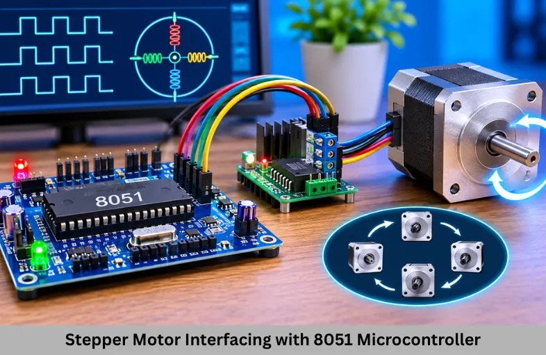
Learn stepper motor interfacing with 8051 microcontroller using ULN2003, Embedded C programming, circuit connections, and practical projects. Embedded Tech Development Academy (ETDA).
- Stepper Motor Interfacing with 8051 Microcontroller
-
Stepper Motor Interfacing with 8051 Microcontroller
- What Is a Stepper Motor?
- Components Required for Stepper Motor Interfacing with 8051
- Circuit Connections for 8051 Stepper Motor Interfacing
- Embedded C Program for Stepper Motor Interfacing
- Controlling Stepper Motor Direction and Speed
- Applications of 8051 Stepper Motor Interfacing
- Learn Microcontroller and Motor Control at ETDA
-
Frequently Asked Questions
- Can a stepper motor be connected directly to an 8051?
- What is the purpose of the ULN2003 driver?
- How can the direction of a stepper motor be changed?
- How is stepper motor speed controlled using 8051?
- What is the difference between full-step and half-step operation?
- Is stepper motor interfacing useful for embedded engineering students?
- Conclusion
Stepper Motor Interfacing with 8051 Microcontroller
Stepper motors are widely used in embedded systems where accurate rotational movement and position control are required. Unlike ordinary DC motors, stepper motors rotate in fixed angular increments, allowing developers to control movement by generating electrical pulse sequences. They are commonly used in CNC machines, printers, robotics, automation equipment, and positioning systems.
Stepper motor interfacing with the 8051 microcontroller is an important practical project for electronics and embedded engineering students. It introduces GPIO programming, motor driver circuits, digital control sequences, and timing concepts. By understanding this project, beginners can develop a foundation for more advanced motor control applications.
Students searching for a Top Embedded Training Institute in Bangalore can explore practical microcontroller projects at Embedded Tech Development Academy (ETDA), where technical learning is supported by hands-on training and assured placement support.
What Is a Stepper Motor?
A stepper motor is an electromechanical device that converts electrical pulses into discrete mechanical movements. Each input sequence energizes specific motor windings, producing magnetic fields that move the rotor by a particular angular step.
The motor’s direction depends on the order in which the windings are energized. Its speed depends on the frequency of the stepping sequence, while its approximate position can be controlled by counting the number of steps generated.
Types of Stepper Motors
Stepper motors are commonly classified into three categories:
Permanent Magnet Stepper Motor: Uses a permanent magnet rotor and electromagnetic stator windings.
Variable Reluctance Stepper Motor: Uses a soft iron rotor that moves toward the energized magnetic field.
Hybrid Stepper Motor: Combines permanent magnet and variable reluctance principles to provide better resolution and performance.
Unipolar and Bipolar Stepper Motors
Unipolar stepper motors typically have winding arrangements with center taps, allowing winding sections to be energized separately. They are comparatively simple to interface using suitable transistor driver circuits.
Bipolar stepper motors have two winding phases without center taps. Their current direction must be reversed through each winding, generally using an H-bridge driver such as L298N or an appropriate dedicated stepper driver.
Step Angle and Motor Resolution
Step angle represents the angular movement produced by one full step. For example, a motor with a 1.8-degree step angle requires 200 full steps for one complete revolution.
[
\text{Steps per revolution}=\frac{360^\circ}{\text{Step angle}}
]
Smaller step angles provide higher positioning resolution. Microstepping drivers can further improve movement resolution, although actual positioning accuracy depends on mechanical and electrical characteristics.
Components Required for Stepper Motor Interfacing with 8051
The basic project requires an 8051 microcontroller development board, a suitable unipolar stepper motor, a ULN2003 driver module, a regulated power supply, and connecting wires.
The ULN2003 contains Darlington transistor arrays that allow low-current microcontroller signals to control higher-current inductive loads. It also includes protection diodes suitable for switching inductive loads when connected according to the manufacturer’s circuit recommendations.
A motor should not be connected directly to 8051 GPIO pins because the microcontroller cannot safely supply the required winding current.
Circuit Connections for 8051 Stepper Motor Interfacing
In this example, a four-phase unipolar stepper motor is connected through a ULN2003 driver. Port 2 of the 8051 generates the control sequence for the driver inputs.
The connections are:
P2.0 → ULN2003 Input IN1
P2.1 → ULN2003 Input IN2
P2.2 → ULN2003 Input IN3
P2.3 → ULN2003 Input IN4
ULN2003 outputs → Corresponding motor winding terminals
Motor supply → Suitable external voltage
8051 ground → Common ground with driver supply
For a typical 28BYJ-48 motor, the motor’s common wire is connected to its specified supply voltage, while the winding wires connect to the driver outputs. The exact wiring order must be verified using the motor and driver documentation.
Embedded C Program for Stepper Motor Interfacing
The following program rotates a unipolar stepper motor using a four-step full-step sequence. The ULN2003 driver receives the control signals generated through Port 2.
Full-Step Excitation Sequence
In full-step operation, two motor phases are energized simultaneously to produce movement. The sequence used in this program is 0x03, 0x06, 0x0C, and 0x09.
Embedded C Code
#include <reg51.h>

unsigned char code step_sequence[4] =
{
    0x03, 0x06, 0x0C, 0x09
};

void delay(void)
{
    unsigned int i, j;

    for(i = 0; i < 200; i++)
        for(j = 0; j < 127; j++);
}

void main(void)
{
    unsigned char i;

    while(1)
    {
        for(i = 0; i < 4; i++)
        {
            P2 = step_sequence[i];
            delay();
        }
    }
}
Understanding Program Execution
The array stores the excitation patterns required to energize the motor windings in sequence. The program continuously sends these patterns to Port 2, creating repeated stepping movement.
The delay determines the interval between successive patterns and influences the motor’s stepping speed. If the delay is reduced excessively, the motor may lose steps, vibrate, or fail to rotate because the rotor cannot follow the commanded sequence.
Controlling Stepper Motor Direction and Speed
The direction of rotation can be reversed by transmitting the excitation sequence in the opposite order. This allows the same 8051 firmware to control clockwise and anticlockwise movement without changing the hardware connections.
Motor speed can be adjusted by changing the time interval between consecutive stepping patterns. Increasing the stepping frequency increases commanded speed, but acceleration should be introduced when starting or stopping under mechanical load.
Half-Step Operation
Half-step operation alternates between single-phase and two-phase excitation. It produces smaller angular increments compared with conventional full-step operation.
For example, a sequence such as 0x01, 0x03, 0x02, 0x06, 0x04, 0x0C, 0x08, and 0x09 can be used for half-step control with the appropriate winding arrangement. This technique can improve movement smoothness and resolution.
Applications of 8051 Stepper Motor Interfacing
Stepper motor interfacing is useful in embedded applications requiring controlled positioning. Students can extend this project into automatic door mechanisms, miniature conveyor systems, robotic platforms, rotating display systems, and simple CNC positioning models.
In industrial automation, stepper motors can control repeatable movements in compact machinery. In Internet of Things (IoT)-based projects, a microcontroller can receive commands through a communication module and control motor movement according to sensor readings or remote instructions.
Learn Microcontroller and Motor Control at ETDA
Embedded Tech Development Academy (ETDA) helps students build practical skills in Embedded C programming, microcontroller interfacing, and firmware development. Projects such as stepper motor interfacing introduce important concepts involving GPIO control, timing, hardware drivers, and real-world debugging.
Students can progress from 8051 programming to ARM Cortex-M development, timers, interrupts, UART, SPI, I2C, RTOS, and Internet of Things (IoT) applications. This learning pathway helps engineering graduates understand how hardware control connects with professional Embedded systems development.
Students evaluating a Top Embedded Training Institute in Bangalore should examine practical laboratory exposure, project-based learning, technical curriculum, and career guidance. Embedded Tech Development Academy (ETDA) combines hands-on training with assured placement support to help learners prepare for embedded engineering opportunities.
Frequently Asked Questions
Can a stepper motor be connected directly to an 8051?
No. A stepper motor requires more current than an 8051 GPIO pin can safely provide. A suitable driver such as ULN2003 or an appropriate H-bridge is required.
What is the purpose of the ULN2003 driver?
ULN2003 amplifies the control capability of microcontroller signals by switching motor winding currents. Its protection diodes help handle inductive voltage transients.
How can the direction of a stepper motor be changed?
The direction can be reversed by changing the order of the winding excitation sequence in the Embedded C program.
How is stepper motor speed controlled using 8051?
Speed is controlled by adjusting the interval between consecutive stepping patterns. Higher stepping frequency produces faster commanded rotation within the motor’s operating limits.
What is the difference between full-step and half-step operation?
Full-step operation moves the rotor through standard step increments, whereas half-step operation alternates single-phase and two-phase excitation to produce smaller movement increments.
Is stepper motor interfacing useful for embedded engineering students?
Yes. It provides practical experience in GPIO programming, driver interfacing, timing control, and firmware development, which are important Embedded Systems skills.
Conclusion
Stepper motor interfacing with the 8051 microcontroller is a valuable project for understanding digital control, motor driver circuits, excitation sequences, and Embedded C programming. Using a ULN2003 driver allows students to control motor winding currents safely while experimenting with speed and direction.
Building this project creates a foundation for advanced motor control, robotics, and automation applications. Students seeking a Top Embedded Training Institute in Bangalore can strengthen these skills at Embedded Tech Development Academy (ETDA) through practical Embedded systems projects, Internet of Things (IoT) exposure, and assured placement support.
Author: ETDA Trainers
Experience: 10+ Years of Industry Experience in Embedded Systems, IoT, and Embedded C Programming