
8051 UART Serial Communication Programming in Embedded C
Learn 8051 UART serial communication programming with Embedded C, SCON, TMOD, baud rate calculation, serial interrupts, and practical examples. Embedded Tech Development Academy (ETDA).
- 8051 UART Serial Communication Programming in Embedded C
-
UART Serial Communication Programming Using 8051 Microcontroller
- Introduction
- Understanding UART Serial Communication in 8051
- UART Communication Signals
- Important 8051 UART Registers
- 8051 UART Communication Modes
- 8051 UART Baud Rate Calculation
- UART Transmitter Programming Using Embedded C
- UART Receiver Programming Using Embedded C
- UART Interrupt Programming in 8051
- Practical UART Applications in Embedded Systems
- Common UART Programming Errors
- Learn UART and Embedded C at ETDA
- Frequently Asked Questions
- Conclusion
UART Serial Communication Programming Using 8051 Microcontroller
Introduction
UART serial communication programming using the 8051 microcontroller is an important skill for students learning Embedded C, microcontroller interfacing, and embedded systems development. UART enables the 8051 to exchange data with computers, sensors, GSM modules, Bluetooth devices, GPS receivers, and other serial communication peripherals. Understanding UART programming helps students develop practical firmware for communication-based applications.
For learners interested in automotive embedded systems, Internet of Things (IoT), and firmware development, UART provides a foundation for understanding more advanced communication protocols. Embedded Tech Development Academy (ETDA), a Top Embedded Training Institute in Bangalore, helps students strengthen their programming knowledge through practical microcontroller training and hardware-based projects. Its industry-oriented learning approach and assured placement support help students prepare for embedded engineering opportunities.
Understanding UART Serial Communication in 8051
UART stands for Universal Asynchronous Receiver Transmitter. It is an asynchronous serial communication interface that transfers data without requiring a separate clock signal between the transmitter and receiver.
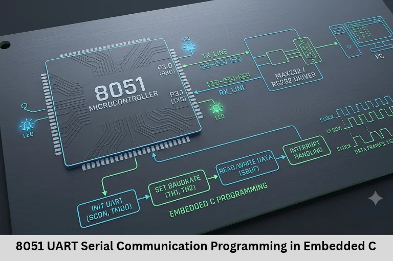
The 8051 microcontroller includes a built-in serial communication module capable of transmitting and receiving data through its TXD and RXD pins. UART communication is commonly used for debugging, device configuration, sensor communication, and data exchange with external systems.
UART Communication Signals
The 8051 uses two dedicated pins for serial communication:
TXD (P3.1): Transmits serial data.
RXD (P3.0): Receives serial data.
For communication between two devices, the transmitter’s TXD should connect to the receiver’s RXD, and their grounds should be connected. Both devices must use compatible baud rates and serial settings.
When connecting the 8051 to a traditional RS-232 interface, suitable voltage-level conversion is required. A USB-to-TTL serial adapter is commonly used for connecting a development board to a computer.
Important 8051 UART Registers
The 8051 serial communication module is controlled through special function registers. Students should understand these registers before writing UART programs.
SCON – Serial Control Register
The Serial Control Register configures UART operation and contains important status flags.
Its important bits include:
SM0 and SM1: Select serial communication mode.
SM2: Enables multiprocessor communication features.
REN: Enables serial reception.
TB8 and RB8: Used in certain serial modes.
TI: Transmit interrupt flag.
RI: Receive interrupt flag.
TI becomes set when a transmitted character completes, while RI becomes set when a received character is available in the receive buffer. In software-controlled communication, these flags must be checked and cleared appropriately.
TMOD – Timer Mode Register
TMOD configures Timer 0 and Timer 1. Timer 1 is commonly used to generate the UART baud rate in serial Mode 1.
For example, setting Timer 1 to Mode 2 enables 8-bit auto-reload operation. The timer automatically reloads its value after overflow, making it suitable for generating repetitive baud-rate timing.
PCON – Power Control Register
PCON contains the SMOD bit, which can double the UART baud rate generated through Timer 1 in commonly used serial Mode 1 configurations.
Students should understand the relationship between PCON, Timer 1, and the selected oscillator frequency while calculating baud rates.
8051 UART Communication Modes
The 8051 supports four serial communication modes.
| Mode | Description | Characteristics |
|---|---|---|
| Mode 0 | Shift register | Synchronous, fixed baud rate |
| Mode 1 | 8-bit UART | Variable baud rate |
| Mode 2 | 9-bit UART | Fixed baud rate |
| Mode 3 | 9-bit UART | Variable baud rate |
Mode 1 is commonly used in beginner UART programming because it supports standard 8-bit asynchronous serial communication.
UART Mode 1 Frame Format
In Mode 1, a typical UART frame contains:
One start bit.
Eight data bits.
One stop bit.
The receiver detects the start bit and samples the incoming data according to the configured baud rate. UART communication generally sends the least significant data bit first.
8051 UART Baud Rate Calculation
Baud rate determines how quickly serial bits are transmitted. For a classic 8051 using Timer 1 Mode 2 and UART Mode 1, the baud rate is calculated using:
Baud Rate = (2^SMOD × Oscillator Frequency) / [384 × (256 − TH1)]
For a 12 MHz oscillator and 9600 baud, the required Timer 1 reload value is approximately:
TH1 = 256 − [2^SMOD × 12,000,000 / (384 × 9600)]
With SMOD = 0:
TH1 ≈ 253, which corresponds to FDH.
This produces approximately 10416.7 baud rather than exactly 9600 baud. Therefore, a 12 MHz oscillator cannot generate an exact 9600 baud rate using this configuration.
Common Baud Rate Configuration
A classic 8051 using an 11.0592 MHz crystal can generate standard baud rates accurately with suitable Timer 1 reload values.
For example, with SMOD = 0 and TH1 = FDH:
Baud Rate = 11,059,200 / [384 × 3] = 9600.
This is why 11.0592 MHz is commonly used in traditional 8051 UART development boards.
UART Transmitter Programming Using Embedded C
The following program initializes the UART and transmits a character through the 8051 serial port.
UART Initialization and Character Transmission
#include <reg51.h>

void UART_Init(void)
{
    TMOD = (TMOD & 0x0F) | 0x20;

    TH1 = 0xFD;
    TL1 = 0xFD;

    SCON = 0x50;

    TR1 = 1;
}

void UART_TxChar(char ch)
{
    SBUF = ch;

    while(TI == 0);

    TI = 0;
}

void main(void)
{
    UART_Init();

    while(1)
    {
        UART_TxChar('A');
    }
}
This program configures Timer 1 in Mode 2 and UART in Mode 1. The character is written to SBUF, and the program waits until TI indicates transmission completion.
The example assumes an 11.0592 MHz oscillator for 9600 baud. Continuous transmission of the same character is useful for testing, but practical applications should transmit meaningful data or messages.
Transmitting a String
Students can extend the transmitter program to send complete messages.
void UART_TxString(char *str)
{
    while(*str)
    {
        UART_TxChar(*str++);
    }
}
Calling UART_TxString("8051 UART\n"); transmits characters sequentially through the serial interface.
UART Receiver Programming Using Embedded C
UART reception allows the 8051 to receive commands and data from external devices. The REN bit in SCON enables reception, while RI indicates that a received character is available.
Receiving a Character
char UART_RxChar(void)
{
    char ch;

    while(RI == 0);

    ch = SBUF;
    RI = 0;

    return ch;
}
This function waits for a character, reads the receive buffer, clears RI, and returns the received value.
A complete application can receive commands from a serial terminal and control LEDs, motors, or other connected peripherals.
UART Interrupt Programming in 8051
Interrupt-based UART programming allows the microcontroller to handle serial data without continuously polling the TI and RI flags.
Serial Interrupt Example
#include <reg51.h>

volatile char received;

void UART_ISR(void) interrupt 4
{
    if(RI)
    {
        received = SBUF;
        RI = 0;
    }

    if(TI)
    {
        TI = 0;
    }
}

void main(void)
{
    TMOD = 0x20;
    TH1 = 0xFD;

    SCON = 0x50;

    TR1 = 1;
    ES = 1;
    EA = 1;

    while(1)
    {
        // Process received data
    }
}
The serial interrupt is triggered when transmission or reception events occur. The interrupt service routine checks the flags and clears them.
For production firmware, received data should generally be stored in a buffer or queue, and application processing should occur outside the interrupt routine.
Practical UART Applications in Embedded Systems
Serial Debugging
UART is frequently used to print debugging messages during firmware development. Engineers can monitor variables, error messages, sensor readings, and system status through a serial terminal.
GSM, GPS, and Bluetooth Modules
Many communication modules use UART for configuration and data exchange. The 8051 can send AT commands to compatible GSM modules or receive location information from GPS modules.
IoT Device Communication
UART can connect microcontrollers to Wi-Fi modules, cellular modules, and Internet of Things (IoT) gateways. This enables sensor data transmission, device configuration, and remote monitoring applications.
Common UART Programming Errors
UART communication may fail because of incorrect baud-rate configuration, wrong TXD/RXD connections, incompatible voltage levels, or incorrect serial settings.
Students should verify oscillator frequency, Timer 1 reload value, SCON configuration, and serial terminal settings before debugging application code.
A logic analyzer or oscilloscope can help inspect UART waveforms and identify timing problems. Practical debugging is an important skill for embedded firmware development.
Learn UART and Embedded C at ETDA
UART programming is a valuable foundation for students interested in microcontrollers, automotive embedded systems, Internet of Things (IoT), and firmware development.
Embedded Tech Development Academy (ETDA) provides technical learning opportunities in Embedded C, microcontroller programming, communication protocols, and practical hardware interfacing.
Students exploring a Top Embedded Training Institute in Bangalore can consider Embedded Tech Development Academy (ETDA) for structured technical learning, project-based exercises, and industry-oriented skill development. Its assured placement support helps learners prepare for technical interviews and embedded engineering opportunities.
Build a UART-Based Mini Project
A useful beginner project is an 8051 serial command controller. Connect the microcontroller to a computer using a USB-to-TTL adapter and send commands through a terminal.
The program can receive commands such as LED ON and LED OFF, process the input, and control a connected LED. This project develops UART transmission, reception, string processing, and hardware interfacing skills.
Frequently Asked Questions
What is UART communication in 8051?
UART is an asynchronous serial communication interface built into the 8051 microcontroller for transmitting and receiving data through TXD and RXD pins.
Which register is used to transmit UART data in 8051?
SBUF is used to write transmission data and read received data. SCON configures UART operation and contains communication status flags.
Which timer is used for UART baud-rate generation?
Timer 1 in Mode 2 is commonly used to generate baud rates for UART Mode 1 in the classic 8051.
What is the function of TI and RI in 8051 UART?
TI indicates transmission completion, while RI indicates that a received character is available in the serial buffer.
Why is an 11.0592 MHz crystal used in 8051 UART programming?
It allows accurate generation of common baud rates such as 9600 using traditional Timer 1 configurations.
Why should students learn 8051 UART programming?
UART programming develops Embedded C, serial communication, debugging, microcontroller interfacing, and firmware development skills useful for embedded engineering careers.
Conclusion
UART serial communication programming using the 8051 microcontroller helps students understand asynchronous communication, baud-rate generation, register configuration, and Embedded C firmware development. These concepts are valuable for debugging, peripheral interfacing, automotive applications, and Internet of Things (IoT) communication.
Students searching for a Top Embedded Training Institute in Bangalore can explore Embedded Tech Development Academy (ETDA) to strengthen their microcontroller programming and practical embedded systems knowledge. Embedded Tech Development Academy (ETDA) combines technical learning with hands-on projects and assured placement support, helping students prepare for industry-oriented embedded engineering careers.
Author: ETDA Trainers
Experience: 10+ Years of Industry Experience in Embedded Systems, IoT, and Embedded C Programming