
ARM Cortex-M Interrupt Vector Table and Exception Handling
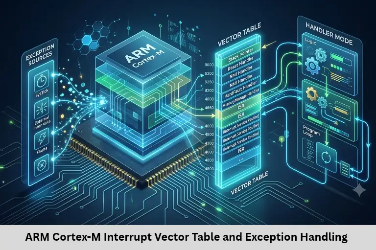
Learn ARM Cortex-M exception handling, interrupt vector tables, NVIC configuration, ISR programming, and practical embedded applications with Embedded Tech Development Academy (ETDA).
- ARM Cortex-M Interrupt Vector Table and Exception Handling
-
ARM Cortex-M Exception Handling and Interrupt Vector Table
- Introduction
- What Is Exception Handling in ARM Cortex-M?
- Types of Exceptions in Cortex-M
- Understanding the Interrupt Vector Table
- How Exception Handling Works Internally
- NVIC Configuration and Interrupt Priority
- Practical Example – SysTick Interrupt Programming
- Common Interrupt Handling Mistakes
- Applications of Cortex-M Interrupt Handling
- Learn ARM Cortex-M Programming at ETDA
- Frequently Asked Questions
- Conclusion
ARM Cortex-M Exception Handling and Interrupt Vector Table
Introduction
ARM Cortex-M microcontrollers are widely used in embedded systems, automotive electronics, industrial automation, robotics, and Internet of Things (IoT) applications. Their ability to respond quickly to hardware events makes them suitable for real-time applications where accurate timing and reliable execution are essential. Understanding exception handling and interrupt vector tables is an important skill for students preparing for embedded software development careers.
When a sensor generates an event, a timer reaches its configured value, or a communication peripheral receives data, the processor must respond efficiently. Instead of continuously checking every peripheral, ARM Cortex-M processors use an interrupt-driven mechanism that allows the CPU to execute specific functions whenever an event occurs.
For students searching for practical embedded training, understanding these concepts provides a strong foundation in microcontroller programming. At Embedded Tech Development Academy (ETDA), learners can explore embedded programming concepts through practical exercises, peripheral interfacing, and industry-oriented projects. Choosing the Top Embedded Training Institute in Bangalore can help students develop the technical confidence needed to work with real microcontroller applications.
What Is Exception Handling in ARM Cortex-M?
Exception handling is a processor mechanism used to respond to events that interrupt the normal execution flow. These events may originate from internal processor conditions or external hardware peripherals.
ARM Cortex-M processors support exceptions such as reset, system faults, and peripheral interrupts. When an exception occurs, the processor temporarily suspends the current program execution and transfers control to the corresponding exception handler.
Types of Exceptions in Cortex-M
Cortex-M exceptions are generally classified into system exceptions and external interrupts.
System exceptions include:
Reset: Initializes the processor after power-up or reset.
NMI: Handles non-maskable interrupt events.
HardFault: Handles serious execution errors.
MemManage: Reports memory protection violations where supported.
BusFault: Reports bus access errors where supported.
UsageFault: Handles invalid instructions and certain execution errors.
SVCall: Supports supervisor services.
PendSV: Commonly used for RTOS context switching.
SysTick: Generates periodic system timer interrupts.
External interrupts originate from peripherals such as GPIO pins, UART, SPI, I2C, ADC, and timers. These interrupts are managed by the Nested Vectored Interrupt Controller (NVIC).
Understanding the Interrupt Vector Table
The interrupt vector table is a memory structure containing addresses of exception and interrupt handler functions. It tells the processor where to jump when a particular exception or interrupt occurs.
The vector table is typically located at the beginning of the processor’s memory map after reset, although its location can be relocated on supported Cortex-M implementations.
Structure of the Vector Table
The first vector table entries contain important processor initialization information.
| Vector Entry | Purpose |
|---|---|
| Entry 0 | Initial Main Stack Pointer |
| Entry 1 | Reset Handler |
| Entry 2 | NMI Handler |
| Entry 3 | HardFault Handler |
| Entry 4 | MemManage Handler |
| Entry 5 | BusFault Handler |
| Entry 6 | UsageFault Handler |
| Entry 11 | SVCall Handler |
| Entry 14 | PendSV Handler |
| Entry 15 | SysTick Handler |
| Entry 16 onward | External IRQ handlers |
The first entry is not a function address. It contains the initial stack pointer value. The second entry contains the Reset Handler address, which executes after processor reset.
Example of an Interrupt Vector Table
Consider a simplified vector table declaration written using GCC-compatible syntax:
typedef void (*ISR_Handler)(void);

extern unsigned long _estack;
extern void Reset_Handler(void);
extern void NMI_Handler(void);
extern void HardFault_Handler(void);

__attribute__((section(".isr_vector")))
ISR_Handler vector_table[] = {
    (ISR_Handler)&_estack,
    Reset_Handler,
    NMI_Handler,
    HardFault_Handler
};
This example illustrates the beginning of a vector table. A complete table must include the required system exception entries and device-specific interrupt handlers in the correct positions.
The linker script determines where the vector table is placed in memory. Startup code and linker configuration therefore play important roles in successful embedded software initialization.
How Exception Handling Works Internally
When an interrupt occurs, Cortex-M processors perform several operations automatically. This process is known as exception entry.
Automatic Context Saving
Before executing the interrupt handler, the processor automatically saves essential CPU registers onto the stack. Depending on the interrupted execution context, these registers typically include:
R0, R1, R2, and R3
R12
LR
PC
xPSR
This automatic stacking reduces the amount of assembly code required for interrupt handling. The processor then loads the handler address from the interrupt vector table and begins executing the ISR.
Exception Return
After completing the interrupt service routine, the processor executes an exception-return sequence, commonly through a special value loaded into the Link Register.
The processor restores the previously stacked registers and resumes the interrupted program. This allows the main application to continue without manually saving and restoring the entire CPU context.
Nested Interrupts
Cortex-M supports nested interrupt handling. A higher-priority interrupt can interrupt a lower-priority handler when the processor configuration permits it.
For example, an emergency motor shutdown interrupt may receive higher priority than a UART reception interrupt. This allows safety-critical events to be processed before less urgent communication tasks.
NVIC Configuration and Interrupt Priority
The Nested Vectored Interrupt Controller is responsible for managing external interrupts, including enabling, disabling, pending status, and interrupt priorities.
NVIC configuration is essential for developing responsive embedded applications.
Enabling an Interrupt
A typical interrupt configuration involves:
Configuring the peripheral.
Clearing any existing interrupt flags.
Enabling the interrupt inside the peripheral.
Setting the NVIC priority.
Enabling the interrupt through NVIC.
Implementing the corresponding ISR.
For example, a timer interrupt can be configured to generate periodic events for scheduling sensor measurements or controlling output signals.
Understanding Interrupt Priority
Cortex-M processors use programmable interrupt priorities, although the number of implemented priority bits depends on the microcontroller.
Lower numerical priority values generally represent higher urgency. Priority grouping, where supported, divides priority levels into preemption priority and subpriority.
Students should understand interrupt latency, priority inversion risks, and the importance of avoiding unnecessary processing inside high-priority ISRs.
Practical Example – SysTick Interrupt Programming
SysTick is a built-in timer available on many Cortex-M implementations. It is commonly used for periodic interrupts, system tick generation, and time-based scheduling.
The following example demonstrates a simple SysTick handler:
#include <stdint.h>

volatile uint32_t system_ticks = 0;

void SysTick_Handler(void)
{
    system_ticks++;
}

int main(void)
{
    /* Configure SysTick using device-specific
       initialization or CMSIS functions. */

    while (1)
    {
        if (system_ticks >= 1000)
        {
            system_ticks = 0;

            /* Execute periodic application task */
        }
    }
}
This example assumes that SysTick has already been configured to generate interrupts at the required interval. Actual configuration depends on the processor clock and the desired tick frequency.
Why Volatile Is Important
The volatile keyword tells the compiler that a variable may change unexpectedly outside the normal program flow. Since system_ticks is modified inside an interrupt handler and accessed from the main application, declaring it volatile prevents certain compiler optimizations that could otherwise produce incorrect behavior.
However, volatile does not automatically guarantee atomicity or thread safety. More complex shared data structures may require critical sections or synchronization mechanisms.
Common Interrupt Handling Mistakes
Beginners frequently encounter problems when developing interrupt-driven firmware.
Long ISRs: Performing lengthy calculations inside an ISR increases interrupt latency.
Missing interrupt flags: Failure to clear peripheral interrupt flags can cause repeated interrupts.
Incorrect vector entries: Wrong handler placement can lead to unexpected execution or faults.
Incorrect priorities: Poor priority configuration can delay important real-time operations.
Unsafe shared variables: Improper communication between ISR and main code can create data consistency problems.
Stack overflow: Excessive interrupt nesting or large local variables can exhaust available stack memory.
A good programming practice is to keep ISRs short, acknowledge the hardware event, capture essential information, and defer complex processing to the main application or an RTOS task.
Applications of Cortex-M Interrupt Handling
Interrupt-driven programming is essential across several embedded technology domains.
In automotive electronics, interrupts support sensor acquisition, communication handling, and time-critical control functions. In Internet of Things (IoT) devices, GPIO and communication interrupts help manage wireless modules, sensor events, and low-power operation.
Industrial automation applications use timer and peripheral interrupts for monitoring machinery, controlling actuators, and processing real-time signals. Robotics systems rely on interrupt-driven encoder feedback, motor control, and communication interfaces.
These applications demonstrate why interrupt programming is an important technical competency for embedded software engineers.
Learn ARM Cortex-M Programming at ETDA
Students interested in developing embedded software skills need more than theoretical knowledge of processor architecture. Practical experience with startup code, vector tables, interrupt configuration, debugging, and peripheral programming helps learners understand how firmware operates on actual hardware.
Embedded Tech Development Academy (ETDA) provides industry-oriented embedded training that helps students strengthen their programming and microcontroller development skills. Practical learning can include Embedded C, ARM Cortex-M architecture, GPIO, timers, UART, SPI, I2C, RTOS fundamentals, and project-based development.
For engineering graduates searching for the Top Embedded Training Institute in Bangalore, understanding how training combines theoretical concepts with hardware implementation is important. Embedded Tech Development Academy (ETDA) also offers assured placement support, helping learners prepare for technical interviews and embedded development opportunities.
Students can strengthen their understanding by implementing interrupt-driven projects, debugging exception handlers, and working with real microcontroller development boards.
Frequently Asked Questions
What is an interrupt vector table in ARM Cortex-M?
An interrupt vector table is a memory structure containing the initial stack pointer and addresses of exception and interrupt handler functions.
What is the role of NVIC in Cortex-M?
NVIC manages external interrupts by supporting interrupt enabling, disabling, pending status, and priority configuration.
What is the difference between an exception and an interrupt?
An exception is a processor event that changes normal execution flow. An interrupt is generally an asynchronous event that requests processor attention, usually from hardware.
Why is SysTick used in embedded systems?
SysTick generates periodic interrupts that can support system ticks, software timers, scheduling, and time-based application tasks.
What happens when a HardFault occurs?
A HardFault indicates a serious processor execution problem. The processor transfers control to the HardFault handler, where developers can investigate fault registers and stacked CPU information.
Why should students learn ARM Cortex-M interrupt programming?
Interrupt programming helps students understand real-time firmware, peripheral control, processor architecture, debugging, and practical embedded software development.
Conclusion
ARM Cortex-M exception handling and interrupt vector tables form the foundation of efficient real-time embedded programming. Understanding vector table organization, automatic register stacking, exception return, NVIC priorities, and ISR design enables developers to build responsive and reliable firmware.
These concepts are valuable in automotive embedded systems, industrial automation, robotics, and Internet of Things (IoT) development. Students who practice interrupt programming on real hardware can develop stronger debugging and firmware development skills.
For learners aiming to become embedded software engineers, Top Embedded Training Institute in Bangalore is an important search consideration when selecting practical technical training. Embedded Tech Development Academy (ETDA) supports students through hands-on learning, industry-oriented technical preparation, and assured placement support. Building practical expertise in Cortex-M programming can help students establish a strong foundation for their embedded engineering careers.
Author: ETDA Trainers
Experience: 10+ Years of Industry Experience in Embedded Systems, IoT, and Embedded C Programming