
Traffic Light Controller Using 8051 Microcontroller
Learn to build a traffic light controller using 8051 microcontroller and Embedded C. Explore LED interfacing, programming, timing and practical implementation. Embedded Tech Development Academy (ETDA).
- Traffic Light Controller Using 8051 Microcontroller
-
Traffic Light Controller Using 8051 Microcontroller
- Introduction
- Understanding the Traffic Light Controller System
- Working Principle of a Traffic Light Controller Using 8051
- Hardware Interfacing with the 8051 Microcontroller
- Writing the Embedded C Program for Traffic Light Control
- Compiling, Testing, and Debugging the Project
- Advanced Improvements to the Traffic Light Controller
- Career Skills Through Embedded Systems Projects at ETDA
-
Frequently Asked Questions
- What is a traffic light controller using an 8051 microcontroller?
- Which programming language is used for this project?
- How many LEDs are required for a two-road traffic light controller?
- Why are timers used in traffic light controllers?
- Can this project be developed using Keil µVision?
- What can students learn from this project?
- Conclusion
Traffic Light Controller Using 8051 Microcontroller
Introduction
A traffic light controller is a practical embedded systems project that demonstrates how microcontrollers automate real-world applications. Traffic signals manage vehicle movement at road intersections by controlling red, yellow, and green lights in a predefined sequence. Developing a traffic light controller using the 8051 microcontroller helps students understand digital output control, timing operations, Embedded C programming, and hardware interfacing.
The 8051 microcontroller is an excellent platform for beginners who want to develop practical embedded engineering skills. This project explains how software instructions control electronic components in real time. For students searching for the Top Embedded Training Institute in Bangalore, gaining practical experience with microcontroller-based projects is essential. Embedded Tech Development Academy (ETDA) provides industry-oriented technical training, hands-on project experience, and assured placement support to help students prepare for embedded engineering careers.
Understanding the Traffic Light Controller System
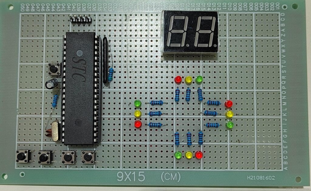
A traffic light controller manages vehicle movement by switching traffic signals according to a predefined timing sequence. A typical intersection uses three signal colours: red for stop, yellow for caution, and green for go.
In an embedded traffic control system, a microcontroller processes programmed instructions and controls connected LEDs through its output pins. The timing sequence ensures that conflicting traffic directions do not receive green signals simultaneously.
Main Components Required
The following hardware and software components are required to develop this project:
8051 microcontroller or development board.
Red, yellow, and green LEDs.
Current-limiting resistors.
Breadboard and connecting wires.
Suitable regulated power supply.
Keil µVision IDE and compatible programmer.
Working Principle of a Traffic Light Controller Using 8051
The 8051 microcontroller controls traffic lights by sending HIGH and LOW signals to its digital output pins. Each LED represents a particular traffic signal, and the Embedded C program determines when it should turn ON or OFF.
For a two-road intersection, one road can represent North-South (NS), while the other represents East-West (EW). When the North-South direction receives a green signal, the East-West direction must remain red. After the green period, the yellow signal provides a warning before traffic stops.
Traffic Signal Operating Sequence
The controller follows a predefined sequence to manage both directions safely:
North-South green and East-West red.
North-South yellow and East-West red.
Both directions red during the transition period.
East-West green and North-South red.
East-West yellow and North-South red.
Both directions red before repeating the cycle.
This sequence repeats continuously using an infinite loop in the Embedded C program.
Hardware Interfacing with the 8051 Microcontroller
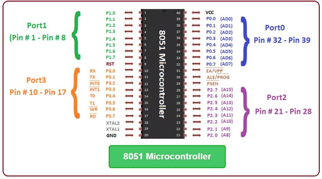
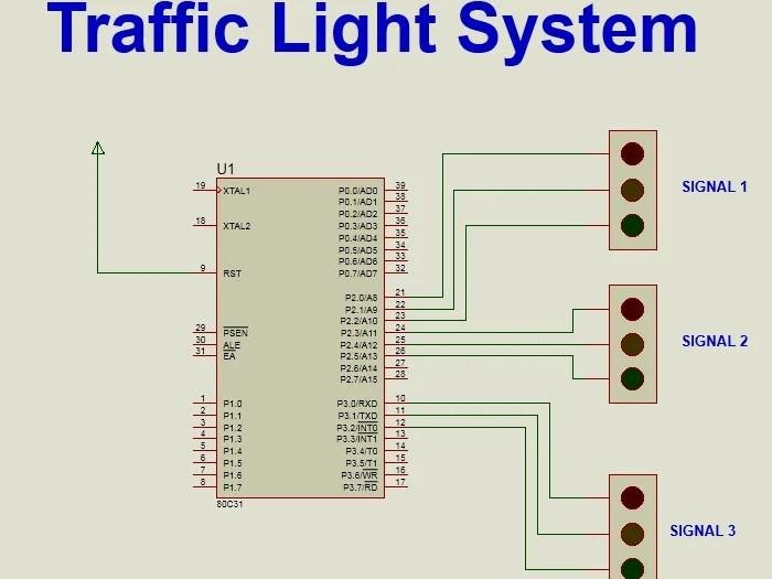
The 8051 provides four 8-bit I/O ports, making it suitable for controlling multiple LEDs and electronic devices. For this project, Port 1 can be used to connect six LEDs representing the two traffic directions.
LED Pin Configuration
| 8051 Pin | LED Function |
|---|---|
| P1.0 | North-South Red |
| P1.1 | North-South Yellow |
| P1.2 | North-South Green |
| P1.3 | East-West Red |
| P1.4 | East-West Yellow |
| P1.5 | East-West Green |
Connect each LED through an appropriate current-limiting resistor. The example assumes active-HIGH LED connections, where a HIGH output switches the LED ON. Check the actual development board circuit because some boards use active-LOW connections.
Writing the Embedded C Program for Traffic Light Control
The program uses individual output pins to control the LEDs and software delay functions to maintain the required signal duration. Students can implement this project using Keil µVision and a compatible 8051 compiler.
Embedded C Program
The following program demonstrates a basic two-road traffic signal sequence using six LEDs connected to Port 1.
#include <REG51.H>

sbit NS_R = P1^0;
sbit NS_Y = P1^1;
sbit NS_G = P1^2;

sbit EW_R = P1^3;
sbit EW_Y = P1^4;
sbit EW_G = P1^5;

void delay(void)
{
    unsigned int i, j;

    for(i = 0; i < 1000; i++)
    {
        for(j = 0; j < 1275; j++)
        {
            ;
        }
    }
}

void main(void)
{
    while(1)
    {
        // North-South Green
        NS_R = 0;
        NS_Y = 0;
        NS_G = 1;
        EW_R = 1;
        EW_Y = 0;
        EW_G = 0;
        delay();

        // North-South Yellow
        NS_G = 0;
        NS_Y = 1;
        EW_R = 1;
        delay();

        // All Red Transition
        NS_Y = 0;
        NS_R = 1;
        EW_R = 1;
        delay();

        // East-West Green
        NS_R = 1;
        EW_R = 0;
        EW_Y = 0;
        EW_G = 1;
        delay();

        // East-West Yellow
        EW_G = 0;
        EW_Y = 1;
        NS_R = 1;
        delay();

        // All Red Transition
        EW_Y = 0;
        EW_R = 1;
        NS_R = 1;
        delay();
    }
}
Understanding the Program Logic
The REG51.H header file provides register definitions required to access the 8051 hardware. The sbit declarations assign meaningful names to individual Port 1 pins, making the program easier to understand and maintain.
The delay() function creates a software delay using nested loops. Inside the infinite while(1) loop, the controller activates the appropriate LEDs in the required sequence. The all-red transition period provides a short interval between the two green phases.
How Does the LED Control Logic Work?
When the program starts, the microcontroller executes the instructions inside the infinite loop. First, P1.2 becomes HIGH, activating the North-South green LED, while the East-West red LED remains ON.
After the delay, the North-South yellow LED becomes active. The controller then enters an all-red transition period before allowing East-West traffic to move. This process continues repeatedly.
Understanding Software Delay and Timing
The nested loops generate a basic software delay by making the processor execute repeated instructions. However, the actual delay depends on oscillator frequency, compiler optimization, and instruction execution time.
For applications requiring accurate timing, hardware timers are preferable. Students can configure Timer 0 or Timer 1 to generate consistent time intervals and use timer interrupts to manage signal changes.
Compiling, Testing, and Debugging the Project
After writing the program, create a project in Keil µVision, select the correct 8051 device, add the source file, and compile the application. Generate the HEX file and transfer it to the development board using a compatible programmer.
Common Errors During Implementation
Incorrect LED connections can produce unexpected signal outputs.
Missing header files can create compilation errors.
Incorrect port configuration can prevent LEDs from switching.
Programming the wrong HEX file can stop the expected sequence.
Incorrect oscillator settings can affect delay timing.
Always verify the hardware connections and test each output before running the complete traffic sequence.
Advanced Improvements to the Traffic Light Controller
After completing the basic project, students can introduce additional features to improve functionality. These enhancements help learners understand how simple microcontroller applications can develop into more advanced embedded systems.
Adding Pedestrian Control and Sensors
A pedestrian push button can be connected to an input pin to request a safe crossing interval. IR sensors can also detect vehicle presence and help modify signal timing based on traffic conditions.
Implementing Timer-Based Control
Hardware timers can replace software delay loops to improve timing accuracy. Students can also explore interrupt-based programming to manage signal transitions efficiently.
Career Skills Through Embedded Systems Projects at ETDA
Developing a traffic light controller gives students practical experience in Embedded C programming, GPIO interfacing, timing operations, and debugging. These concepts are useful in automotive electronics, industrial automation, smart infrastructure, and Internet of Things (IoT)-based applications.
Practical Embedded C Training for Students
At Embedded Tech Development Academy (ETDA), students can strengthen their technical knowledge through structured Embedded C programming and microcontroller training. The learning process focuses on hardware connections, writing efficient code, debugging errors, and developing working projects.
Building Industry-Ready Embedded Skills
For students looking for the Top Embedded Training Institute in Bangalore, practical exposure is important because embedded engineering requires both programming knowledge and hardware understanding. Embedded Tech Development Academy (ETDA) combines technical learning with hands-on project experience and assured placement support, helping learners prepare for technical interviews and embedded development opportunities.
Frequently Asked Questions
What is a traffic light controller using an 8051 microcontroller?
It is an embedded systems project that uses the 8051 microcontroller to control red, yellow, and green traffic LEDs according to a programmed sequence.
Which programming language is used for this project?
Embedded C is commonly used because it allows developers to control 8051 registers, I/O ports, and timers efficiently.
How many LEDs are required for a two-road traffic light controller?
Six LEDs are required for a basic two-road intersection, with three LEDs representing each direction.
Why are timers used in traffic light controllers?
Timers provide controlled time intervals for changing traffic signals. Hardware timers offer more reliable timing than approximate software delay loops.
Can this project be developed using Keil µVision?
Yes. Keil µVision can be used to write, compile, and debug the Embedded C program before generating a HEX file for the 8051 microcontroller.
What can students learn from this project?
Students learn Embedded C programming, GPIO interfacing, LED control, timing operations, hardware debugging, and basic real-time embedded system design.
Conclusion
A traffic light controller using the 8051 microcontroller is an excellent beginner-level project for understanding real-time hardware control. It teaches students how to interface LEDs, configure digital output pins, develop timing sequences, and execute Embedded C programs on a microcontroller.
Students can improve the project by adding pedestrian switches, vehicle sensors, timer interrupts, and intelligent traffic management features. Choosing the Top Embedded Training Institute in Bangalore can help aspiring engineers gain the practical skills required for the embedded industry. Embedded Tech Development Academy (ETDA) supports students through hands-on technical training, real-time projects, and assured placement support, helping them build a strong foundation for careers in embedded systems.
Author: ETDA Trainers
Experience: 10+ Years of Industry Experience in Embedded Systems, IoT, and Embedded C Programming