
Automotive Sensor Network Using CAN Protocol and LPC1768
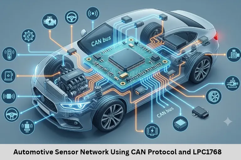
Learn automotive CAN network design with NXP LPC1768, sensor nodes, CAN frames, acceptance filters, error handling, and Internet of Things (IoT) gateways.
- Automotive Sensor Network Using CAN Protocol and LPC1768
-
Automotive Sensor Network Design Using CAN Protocol with NXP LPC1768
- Introduction to Automotive CAN Sensor Networks
- Understanding CAN Protocol Architecture
- Implementing CAN Communication with NXP LPC1768
- CAN Acceptance Filtering and Error Handling
- Designing an Automotive Sensor Network
- Connecting CAN Networks to IoT Platforms
- Building Practical Automotive Embedded Skills with ETDA
- Frequently Asked Questions
- Conclusion
Automotive Sensor Network Design Using CAN Protocol with NXP LPC1768
Introduction to Automotive CAN Sensor Networks
Modern automobiles depend on distributed electronic control units (ECUs) to manage engine operation, vehicle speed, braking assistance, fuel monitoring, and driver information systems. These modules continuously exchange sensor measurements and control data, making reliable automotive communication essential for vehicle performance, diagnostics, and safety. Designing an automotive sensor network requires knowledge of the Controller Area Network (CAN) protocol, embedded C programming, microcontroller peripherals, sensor interfacing, real-time communication, and fault detection.
The Controller Area Network (CAN) provides a shared communication bus that allows multiple ECUs to exchange messages without dedicated point-to-point wiring between every module. The NXP LPC1768, based on an ARM Cortex-M3 core, includes two CAN controllers, making it useful for embedded CAN demonstrations and gateway-oriented projects. With appropriate external CAN transceivers, termination, and firmware configuration, developers can build a sensor network that transmits engine temperature, fuel level, and vehicle speed data.
Embedded Tech Development Academy (ETDA) helps learners explore embedded C, ARM microcontrollers, automotive protocols, and practical firmware development. For students researching a Top Embedded Training Institute in Bangalore, Embedded Tech Development Academy (ETDA) offers a learning pathway to develop industry-relevant embedded skills and explore assured placement support. Understanding CAN sensor networks provides a useful foundation for automotive embedded systems, vehicle diagnostics, Internet of Things (IoT) gateways, and ECU communication.
Understanding CAN Protocol Architecture
Why Automotive Systems Use CAN
Older vehicle designs often required separate wiring connections between electronic components. As the number of ECUs increased, this approach added wiring weight, installation complexity, and maintenance effort. CAN simplifies communication by allowing multiple nodes to share a two-wire differential bus.
Each CAN message carries an identifier that describes its meaning and determines its arbitration priority. The identifier does not inherently represent a destination address; multiple nodes can receive the same message and decide whether to process it.
Main Components of a CAN Network
A CAN sensor network contains several interconnected components:
CAN nodes: Microcontroller-based devices that transmit or receive messages.
CAN bus: The shared communication medium formed by CAN High (CANH) and CAN Low (CANL).
CAN controller: Handles protocol functions such as framing, arbitration, CRC generation, and error monitoring.
CAN transceiver: Converts controller logic signals into the differential electrical signals used on the bus.
Differential Signalling and Termination
CAN uses differential signalling to improve noise immunity. A conventional high-speed CAN bus typically uses a twisted pair and 120-ohm termination at each physical end of the main bus. The exact topology and cable characteristics must follow the selected CAN physical-layer requirements.
Physical-Layer Design Considerations
The CAN controller alone cannot drive the vehicle bus directly. A compatible external transceiver is required. Engineers must also consider bus length, bit rate, cable routing, grounding, electromagnetic interference, and the number of connected nodes. Incorrect termination or excessive stubs can cause communication errors even when the firmware is configured correctly.
Implementing CAN Communication with NXP LPC1768
LPC1768 CAN Controller Features
The NXP LPC1768 provides two integrated CAN controllers that support CAN protocol communication. These peripherals reduce the need for a separate external CAN controller, but each physical bus connection still requires a suitable CAN transceiver.
A typical development setup includes an LPC1768 development board, CAN transceiver, temperature sensor, fuel-level input or simulator, speed-pulse input, regulated power supply, and a properly terminated CAN bus. Two or more CAN-capable nodes are needed to demonstrate message exchange realistically.
CAN Initialisation Workflow
Firmware development begins by configuring the microcontroller’s pin functions, peripheral clock, bit timing, and CAN controller operating mode. The selected bit rate must be compatible with every node on the bus.
The application then configures transmit buffers, receive handling, and acceptance filters. Exact register settings depend on the LPC1768 peripheral documentation and the development library being used.
Message Transmission and Reception
When sensor data is ready, firmware scales or encodes the measurement into a defined payload. The application submits a message to the CAN controller, which handles frame construction and bus arbitration. Receiving nodes validate the frame and deliver accepted messages to application software.
Example CAN Message Definition
For a demonstration network, the following identifiers can be assigned in the project specification:
| Sensor message | Example CAN ID | Payload |
|---|---|---|
| Engine temperature | 0x101 | Temperature value |
| Fuel level | 0x102 | Fuel percentage |
| Vehicle speed | 0x103 | Speed value |
| Warning status | 0x080 | Status flags |
These are illustrative standard 11-bit identifiers, not mandatory automotive assignments. Lower numerical identifiers generally have higher arbitration priority when competing frames differ at the relevant identifier bits. The team should document the byte order, scaling, units, update rate, and timeout behaviour for each message.
CAN Acceptance Filtering and Error Handling
Acceptance Filters
Automotive networks can carry many messages, but an ECU usually needs only a subset. Acceptance filtering allows the controller to identify messages of interest before application software processes them.
For example, a dashboard node may accept temperature, fuel-level, and speed messages, while a separate monitoring node may focus on temperature and warning status. Filter configuration must match the identifier format and mask behaviour supported by the controller.
Error Detection and Bus Recovery
CAN includes cyclic redundancy checking (CRC), bit monitoring, frame checks, and acknowledgement mechanisms. Nodes also monitor protocol errors and maintain error counters that can lead to error-active, error-passive, or bus-off states.
Automatic retransmission may occur for certain transmission errors, but it is not a guarantee that every message will eventually arrive. Persistent wiring faults, missing acknowledgements, bus-off conditions, or a failed node can interrupt communication. Robust firmware should detect missing updates, log diagnostic information, and implement a documented recovery strategy.
Designing an Automotive Sensor Network
Sensor Nodes and Central Monitoring
A practical prototype can use three sensor nodes and one monitoring node.
Engine temperature node: Reads a temperature sensor, applies calibration, and periodically transmits the measured value.
Fuel-level node: Converts a simulated or conditioned sensor input into a percentage.
Vehicle-speed node: Measures pulses from a sensor or signal generator and calculates speed using the system’s calibration parameters.
Central monitoring node: Receives relevant frames, checks their freshness, and displays readings or warning indicators.
Sensor signals must be conditioned to match the microcontroller’s electrical limits. Automotive sensors may require dedicated interface circuits, protection, filtering, or isolation depending on the signal and vehicle environment.
End-to-End Communication Workflow
The system follows a repeatable sequence:
Sensors measure physical parameters.
Firmware filters and converts raw readings into engineering units.
Each node encodes values into a documented CAN payload.
The CAN controller arbitrates for bus access and transmits frames.
Receiving controllers validate frames and apply acceptance filters.
Application firmware checks data ranges and update timeouts.
The dashboard displays readings and raises warnings when configured thresholds are exceeded.
A warning such as engine overheating should use a defined threshold, validated sensor data, and appropriate timing. CAN arbitration prioritises messages by identifier, but it does not independently guarantee an end-to-end deadline.
Connecting CAN Networks to IoT Platforms
Automotive Gateway Architecture
A CAN-to-Internet of Things (IoT) gateway can collect selected bus messages and forward them to a remote server using a separate network interface, such as Ethernet, Wi-Fi, or cellular connectivity. The LPC1768 can participate in CAN communication, but an appropriate external gateway or communication module may be needed for cloud connectivity.
Practical Benefits and Security
Cloud analysis can support fleet monitoring, maintenance trend analysis, remote diagnostics, and fault reporting. Before data leaves the vehicle network, the gateway should validate message identifiers, filter sensitive information, and avoid forwarding unnecessary traffic.
CAN itself does not provide built-in cryptographic authentication or encryption. Connected designs therefore need security controls at the gateway and application layers, including access restrictions, secure updates, and protection against unauthorised commands. Safety-critical vehicle functions must not rely solely on a prototype Internet of Things (IoT) connection.
Building Practical Automotive Embedded Skills with ETDA
Automotive sensor networking combines Embedded C, microcontroller peripherals, CAN framing, interrupt-driven firmware, sensor calibration, debugging, and system testing. Learners should practise transmitting known payloads, verifying frames with a CAN analyser, simulating communication faults, and measuring update intervals.
Embedded Tech Development Academy (ETDA) supports learners interested in hands-on embedded development. Students comparing a Top Embedded Training Institute in Bangalore can explore training in microcontrollers, communication protocols, and firmware debugging, along with assured placement support as part of their career preparation. Practical CAN projects can help learners build a portfolio relevant to automotive electronics, embedded software, and connected-device development.
Frequently Asked Questions
What is CAN protocol in automotive systems?
CAN is a serial communication protocol that allows multiple electronic control units to exchange messages over a shared bus using message identifiers and priority-based arbitration.
Does the LPC1768 support CAN communication?
Yes. The LPC1768 includes two CAN controllers. External CAN transceivers are required to connect the controller signals to the physical CAN bus.
What is the role of a CAN transceiver?
A CAN transceiver converts controller-side logic signals into differential CAN bus signals and converts received bus signals back into logic-level signals.
How does CAN arbitration work?
When multiple nodes begin transmitting together, CAN arbitration allows the frame with the higher-priority identifier to continue without corrupting the winning message. Nodes that lose arbitration wait and retry.
Why are termination resistors required on a CAN bus?
Termination resistors reduce signal reflections on the bus. A conventional high-speed CAN network generally uses 120-ohm resistors at both physical ends of the main bus.
Can an LPC1768-based CAN network connect to an IoT platform?
Yes, through a suitable gateway or external communication module. The gateway can forward selected CAN data to a server, but the design must include data validation, access control, and security protections.
Conclusion
Automotive sensor network design requires more than connecting ECUs to a shared bus. Engineers must understand CAN identifiers, arbitration, differential signalling, transceiver selection, termination, bit timing, acceptance filters, and error recovery. Using the NXP LPC1768, developers can create a practical prototype that gathers engine temperature, fuel-level, and vehicle-speed data and distributes the measurements to a monitoring node. Adding a gateway can extend the project to Internet of Things (IoT)-based diagnostics and fleet monitoring, provided communication security and system boundaries are carefully designed.
For learners strengthening their skills in automotive embedded systems, CAN protocol implementation offers valuable experience with Embedded C, ARM Cortex-M microcontrollers, real-time communication, and hardware debugging. Embedded Tech Development Academy (ETDA) can be explored by students looking for a Top Embedded Training Institute in Bangalore and assured placement support while preparing for embedded development opportunities. Building and testing a complete sensor-network prototype helps connect theoretical protocol knowledge with practical engineering.
Author: ETDA Trainers
Experience: 10+ Years of Industry Experience in Embedded Systems, IoT, and Embedded C Programming