
Bare-Metal Firmware Development on Custom ASICs
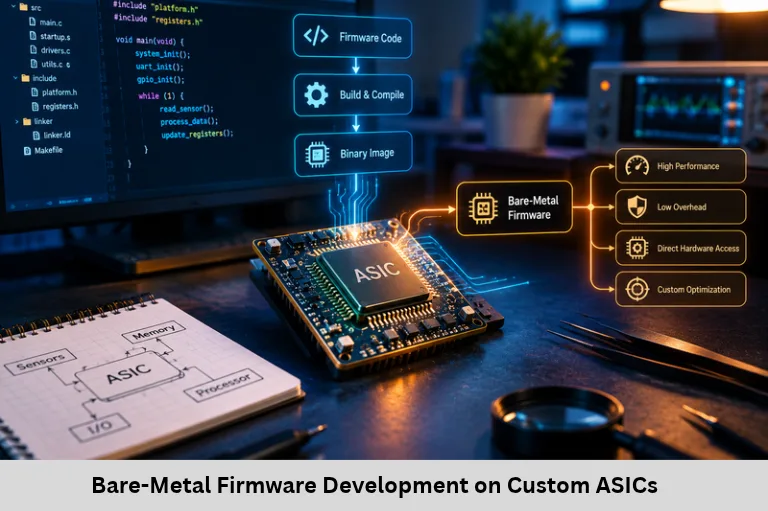
Learn custom ASIC bare-metal firmware development, boot architecture, memory maps, startup code, FPGA prototyping, silicon bring-up, and validation. Embedded Tech Development Academy (ETDA).
- Bare-Metal Firmware Development on Custom ASICs
-
A Comprehensive Look at Bare-Metal Firmware Development on Custom ASICs
- Introduction to Bare-Metal Firmware for Custom ASICs
- What Is Bare-Metal Firmware?
- The Custom ASIC Firmware Development Process
- FPGA Prototyping and Silicon Bring-Up
- Challenges in Custom ASIC Development
- Best Practices for Reliable ASIC Firmware
-
Frequently Asked Questions
- What is bare-metal firmware on a custom ASIC?
- Why is ASIC firmware development more challenging than microcontroller firmware?
- What is the role of a linker script in ASIC firmware?
- Why is FPGA prototyping important before ASIC fabrication?
- What is silicon bring-up?
- Can firmware fix a defective ASIC?
- Conclusion
A Comprehensive Look at Bare-Metal Firmware Development on Custom ASICs
Introduction to Bare-Metal Firmware for Custom ASICs
Bare-metal firmware development for a custom Application-Specific Integrated Circuit (ASIC) is one of the most demanding areas of embedded engineering. Unlike conventional microcontrollers, which often provide documented peripherals, vendor software development kits, startup code, and established debugging tools, a custom ASIC may require the engineering team to define much of the low-level software infrastructure from scratch. This includes reset handling, processor initialisation, memory configuration, clock control, peripheral register access, and hardware validation.
The challenge becomes greater when firmware and hardware are developed simultaneously. Firmware engineers must work closely with digital design, register-transfer-level (RTL), verification, and silicon teams to ensure that software correctly controls the implemented hardware. Skills in Embedded C, assembly language, linker scripts, processor architecture, FPGA prototyping, and silicon bring-up are therefore essential.
These techniques are important across advanced Embedded Systems, custom processors, system-on-chip (SoC) platforms, and specialised Internet of Things (IoT) hardware. Embedded Tech Development Academy (ETDA) supports learners exploring practical embedded development concepts. Students researching a Top Embedded Training Institute in Bangalore can explore technical learning opportunities and assured placement support while building a foundation in low-level programming, microcontrollers, and firmware debugging. Although custom ASIC work requires specialised hardware knowledge, the underlying Embedded Systems principles provide a useful starting point.
What Is Bare-Metal Firmware?
Direct Hardware Control Without an Operating System
Bare-metal firmware executes directly on a processor without a conventional operating system or scheduler. It controls hardware through registers, processor instructions, interrupts, and carefully designed software routines.
Typical early-stage responsibilities include:
Establishing the processor’s initial execution environment.
Configuring clocks, reset controls, and power domains.
Initialising SRAM and external memory interfaces.
Configuring custom peripherals and communication interfaces.
Running built-in self-tests (BIST) and early hardware diagnostics.
Why ASIC Firmware Is Different
A custom ASIC may not include familiar peripheral blocks or a standard software ecosystem. Its registers, reset values, memory map, and boot sequence are defined by the chip architecture and RTL implementation. Engineers must use approved hardware specifications rather than assume that register layouts match those of existing microcontrollers.
Relationship Between Firmware and RTL
RTL describes the digital logic that implements the processor, memory controllers, and peripherals. Firmware operates that hardware through its defined programming interface. If a register is incorrectly specified, implemented, or documented, the firmware may behave unexpectedly even when the software logic is correct.
The Custom ASIC Firmware Development Process
Step 1 — Define the Boot Architecture and Memory Map
Before writing startup code, the engineering team must document the processor’s reset entry point, boot ROM, SRAM regions, peripheral address ranges, and any external memory or flash interfaces.
The memory map determines where code and data can reside. It also guides linker-script development and the placement of stack, heap, initialized data, and uninitialized data sections.
Step 2 — Build the Toolchain and Startup Code
A supported compiler, assembler, linker, and debugging workflow are required. Depending on the processor architecture, the toolchain may use GCC, LLVM/Clang, or another suitable compiler.
Startup code typically establishes the stack pointer, initialises required processor state, copies initialised data into RAM, clears the BSS region, and transfers control to the C runtime or application entry point. The exact sequence depends on the processor, boot architecture, and security configuration.
Linker Scripts and Runtime Initialisation
A linker script specifies where code and data sections are placed. Incorrect section placement can cause boot failures, invalid memory accesses, or corruption. The team must also define how the firmware handles exceptions, interrupts, and unexpected processor states.
Cross-Compilation and Reproducible Builds
A cross-compiler generates executable code for the target processor from a development host. Reproducible build scripts, version-controlled toolchain settings, linker maps, and build logs help teams identify differences between firmware releases during hardware development.
Step 3 — Create Hardware Abstraction and Register Definitions
Custom peripheral drivers begin with the hardware register specification. Engineers define memory-mapped register addresses, bit fields, masks, reset values, and access permissions, then implement routines for initialisation and operation.
For example, a clock-control driver may enable a peripheral clock, wait for a ready-status bit, and verify the resulting state before continuing.
Register definitions can be generated from structured descriptions using formats and tools such as SystemRDL or IP-XACT, depending on the project’s workflow. Generated code still requires review, version control, and verification against the implemented RTL.
FPGA Prototyping and Silicon Bring-Up
Step 4 — Validate Firmware Before Fabrication
Manufacturing an ASIC is expensive, so teams usually test firmware before the first silicon becomes available. Simulation, hardware emulation, and FPGA prototyping can expose many functional problems earlier.
Emulation platforms and FPGA prototypes allow engineers to check register access, boot sequencing, peripheral operation, and memory interfaces. An FPGA prototype may differ from the final ASIC in timing, resources, and peripheral implementation, so successful FPGA testing does not guarantee that silicon will behave identically.
Step 5 — Bring Up the First Silicon
Silicon bring-up begins when fabricated chips arrive from the manufacturer. Engineers typically start with power and reset checks, then verify processor execution and initialise clocks, memory, and essential peripherals.
A common early milestone is obtaining a UART debug message. This confirms that enough of the boot path is functioning to execute code and communicate diagnostic information.
Initial Hardware Validation
The team may run memory tests, BIST routines, clock checks, interface loopback tests, and peripheral register tests. Where available, JTAG, trace hardware, and on-chip debug facilities improve visibility. If these features are limited, engineers may rely on UART output, GPIO status signals, and diagnostic registers.
Silicon Validation Firmware
Validation firmware exercises hardware features systematically, including supported clock frequencies, power states, memory interfaces, and error-handling paths. Test results should be recorded against the relevant silicon revision and RTL specification.
Challenges in Custom ASIC Development
Hardware-Software Co-Verification
A failure during bring-up may originate from firmware, RTL logic, timing constraints, reset sequencing, or clock-domain crossing. Engineers must compare register behaviour with the specification, examine waveforms where possible, and reproduce failures using controlled tests.
Limited Debugging and Hardware Defects
A custom chip may have incomplete debugging facilities during early revisions. Furthermore, a manufacturing run can reveal defects that cannot be physically corrected in the delivered silicon.
Where supported by the architecture, workarounds may include firmware changes, disabling a faulty feature, altering configuration sequences, or applying approved boot-time patches. Such workarounds must be validated carefully and cannot fix every hardware defect.
Best Practices for Reliable ASIC Firmware
Specification Control and Automated Testing
Maintain synchronised versions of RTL, register descriptions, firmware, and validation tests. Automate repeatable tests for each peripheral and run them across simulation, FPGA, and silicon environments where practical.
Defensive programming should check hardware-ready flags, timeout conditions, invalid configuration values, and unexpected status bits. Error paths must avoid indefinite waits whenever the hardware specification allows a timeout or recovery mechanism.
Plan for Boot Recovery and Patchability
If the chip architecture supports it, design a documented recovery mechanism before tape-out. Options may include ROM patch hooks, shadow ROM, RAM-resident patches, or controlled microcode updates where applicable. Not every ASIC supports all these mechanisms, so feasibility must be established during architecture design.
Embedded Tech Development Academy (ETDA) can be explored by learners building foundational skills in Embedded Systems, Embedded C, processor architecture, and firmware debugging. Students comparing a Top Embedded Training Institute in Bangalore may consider practical learning options and assured placement support while preparing for embedded development careers. Internet of Things (IoT) and custom ASIC applications both benefit from disciplined low-level software engineering, although their hardware requirements can differ substantially.
Frequently Asked Questions
What is bare-metal firmware on a custom ASIC?
It is low-level software that directly controls a custom chip’s processor and peripherals without relying on a conventional operating system.
Why is ASIC firmware development more challenging than microcontroller firmware?
Custom ASICs may lack standard startup files, vendor libraries, familiar peripherals, and established debugging tools, requiring engineers to build and validate more of the software infrastructure themselves.
What is the role of a linker script in ASIC firmware?
A linker script places code and data into defined memory regions and helps the firmware match the chip’s memory map.
Why is FPGA prototyping important before ASIC fabrication?
It allows engineers to test firmware and hardware behaviour before manufacturing, reducing the risk of discovering avoidable functional issues in the first silicon.
What is silicon bring-up?
Silicon bring-up is the initial process of checking a newly manufactured chip, establishing basic execution, configuring clocks and memory, and validating essential hardware functions.
Can firmware fix a defective ASIC?
Firmware can work around some defects if the hardware architecture permits it, but it cannot correct every physical or logic defect. Some issues require a revised silicon design.
Conclusion
Bare-metal firmware development on a custom ASIC combines processor initialisation, memory management, register-level programming, hardware validation, and close collaboration between software and digital design teams. The development journey starts with a defined memory map and boot architecture, continues through toolchain construction and peripheral drivers, and advances through FPGA prototyping, first-silicon bring-up, and systematic validation.
Reliable results depend on accurate specifications, reproducible builds, automated tests, effective debugging, and carefully planned recovery mechanisms. These practices are valuable throughout Embedded Systems engineering, including custom SoCs, specialised Internet of Things (IoT) devices, and processor-based hardware. Embedded Tech Development Academy (ETDA) is an option for learners strengthening their foundations in embedded programming and hardware-software integration. Those researching a Top Embedded Training Institute in Bangalore can explore relevant technical learning opportunities and assured placement support as part of their career preparation.
Author: ETDA Trainers
Experience: 10+ Years of Industry Experience in Embedded Systems, IoT, and Embedded C Programming