
CAN vs SPI vs I2C: Communication Protocols Explained
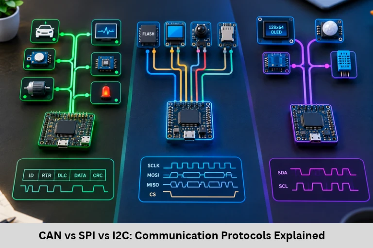
Compare CAN, SPI, and I²C communication protocols, including wiring, timing, data rates, frame formats, applications, and embedded systems design. Embedded Tech Development Academy (ETDA).
- CAN vs SPI vs I2C: Communication Protocols Explained
-
CAN, SPI, and I²C Described: A Comprehensive Overview of Communication Protocols
- Introduction to Embedded Communication Protocols
- SPI (Serial Peripheral Interface): Working Principle
- I²C (Inter-Integrated Circuit): Two-Wire Communication
- CAN (Controller Area Network): Reliable Multi-Node Communication
- CAN vs SPI vs I²C: Key Differences
- Selecting the Right Communication Protocol
- Frequently Asked Questions
- Conclusion
CAN, SPI, and I²C Described: A Comprehensive Overview of Communication Protocols
Introduction to Embedded Communication Protocols
Communication protocols are essential to embedded systems because they define how microcontrollers, sensors, memory devices, actuators, and electronic control units exchange data. From reading temperature sensors to controlling automotive braking systems, reliable communication enables hardware components to coordinate their operations. CAN, SPI, and I²C are widely used protocols, each designed for different requirements involving speed, wiring, distance, and reliability.
Serial communication protocols transmit data one bit at a time over communication lines. SPI (Serial Peripheral Interface) supports high-speed communication with peripherals, I²C (Inter-Integrated Circuit) simplifies connections between multiple integrated circuits, and CAN (Controller Area Network) provides robust, message-based communication between distributed controllers in electrically noisy environments.
Understanding SPI clock polarity and phase, I²C addressing and acknowledgements, CAN arbitration and error detection, baud rates, timing diagrams, and electrical interfaces is important for embedded firmware development and hardware debugging. These concepts help engineers select the appropriate protocol for sensor interfacing, automotive electronics, industrial automation, and Internet of Things (IoT) devices.
Embedded Tech Development Academy (ETDA) supports technical learning in embedded systems and microcontroller communication. Students searching for a Top Embedded Training Institute in Bangalore can explore Embedded Tech Development Academy (ETDA)‘s practical training approach and assured placement support while developing industry-relevant skills.
SPI (Serial Peripheral Interface): Working Principle
What Is SPI?
SPI is a synchronous serial communication protocol commonly used for short-distance communication between a controller and peripheral devices. It typically operates in a controller-peripheral architecture, with the controller generating the clock and selecting the peripheral.
SPI Signal Lines and Architecture
Four Main SPI Signals
MOSI: Master Out, Slave In; carries data from controller to peripheral.
MISO: Master In, Slave Out; carries data from peripheral to controller.
SCK: Serial Clock; synchronizes data transfer.
CS/SS: Chip Select or Slave Select; activates the selected peripheral.
SPI supports full-duplex communication because transmission and reception can occur simultaneously. Multiple peripherals can share clock and data lines, although separate chip-select lines are commonly used.
SPI Data Transfer and Timing Modes
SPI commonly uses shift registers at both ends. The controller generates SCK, and data is sampled and shifted according to the configured clock polarity (CPOL) and clock phase (CPHA).
Understanding the Four SPI Modes
Mode 0: CPOL = 0, CPHA = 0.
Mode 1: CPOL = 0, CPHA = 1.
Mode 2: CPOL = 1, CPHA = 0.
Mode 3: CPOL = 1, CPHA = 1.
The correct mode depends on the peripheral datasheet. SPI transfers commonly use 8-bit words, although other word lengths are possible.
SPI Applications
SPI is frequently used with OLED displays, SD cards, external flash memory, high-speed ADCs, DACs, and radio modules. Its high throughput and simple transfer mechanism make it suitable for peripherals requiring frequent data exchanges.
I²C (Inter-Integrated Circuit): Two-Wire Communication
What Is I²C?
I²C is a synchronous, address-based serial bus originally developed by Philips, now NXP. It uses two shared signal lines to connect multiple compatible devices to a controller or controllers.
SDA, SCL and Device Addressing
I²C Signal Lines
SDA: Serial Data Line, which carries address and data bits.
SCL: Serial Clock Line, which synchronizes communication.
Both lines normally use pull-up resistors because I²C devices use open-drain or open-collector signalling. The appropriate pull-up values depend on bus capacitance, supply voltage, device sink-current capability, and required speed.
I²C supports 7-bit and 10-bit addressing. Multiple devices can share the same bus, provided their addresses do not conflict.
I²C Frame Structure and Data Transfer
A typical I²C transaction begins with a START condition, followed by a slave address and read/write bit. The receiver responds with an acknowledgement bit, after which data bytes can be exchanged. A STOP condition ends the transaction.
START, STOP and ACK/NACK Conditions
START: SDA transitions from HIGH to LOW while SCL is HIGH.
STOP: SDA transitions from LOW to HIGH while SCL is HIGH.
ACK: The receiver pulls SDA LOW during the acknowledgement clock.
NACK: SDA remains HIGH during the acknowledgement clock.
Each byte is followed by an acknowledgement clock. A NACK may indicate that a device is unavailable, a transfer has completed, or the receiver does not wish to accept another byte.
I²C Speed Modes and Applications
Common I²C modes include Standard-mode at 100 kbit/s, Fast-mode at 400 kbit/s, Fast-mode Plus at 1 Mbit/s, and High-speed mode at 3.4 Mbit/s. Actual operation depends on device capabilities and electrical conditions.
I²C is widely used for temperature sensors, accelerometers, real-time clocks, EEPROMs, and low-speed peripheral configuration.
CAN (Controller Area Network): Reliable Multi-Node Communication
What Is CAN?
CAN is a robust, message-based serial communication protocol developed by Bosch and widely used in automotive and industrial systems. It allows multiple nodes to communicate over a shared bus without requiring a central controller to schedule every transmission.
CAN Bus Wiring and Differential Signalling
CAN_H and CAN_L
A conventional high-speed CAN network uses two differential signal lines: CAN_H and CAN_L. The receiver interprets the voltage difference between them, improving resistance to common-mode electrical noise.
High-speed CAN networks commonly require termination resistors at both physical ends of the main bus, typically 120 Ω each, subject to the network design. A CAN transceiver connects the controller’s logic signals to the physical bus.
CAN Frames, Arbitration and Error Detection
CAN messages contain fields such as an identifier, control information, data, a cyclic redundancy check (CRC), acknowledgement, and end-of-frame bits. Classic CAN supports up to 8 data bytes per frame, while CAN FD supports up to 64 data bytes.
Message Arbitration
When multiple nodes begin transmitting simultaneously, CAN uses bitwise arbitration. A dominant bit (0) overrides a recessive bit (1). A node that transmits a recessive bit but reads a dominant bit during arbitration stops transmitting and retries later.
For messages competing on the same bus, a lower numerical identifier generally has higher arbitration priority.
CAN Error Handling
CAN includes bit monitoring, bit stuffing checks, CRC checking, frame-format checks, and acknowledgement checking. Error counters help a node transition between error-active, error-passive, and bus-off states as defined by the protocol.
CAN Data Rates and Applications
Classic CAN commonly supports data rates up to 1 Mbit/s, depending on network length and physical conditions. CAN FD can support a faster data phase, with rates dependent on the controller, transceiver, topology, and system design.
CAN is used in engine control units, anti-lock braking systems, industrial robots, vehicle networks, and automation equipment.
CAN vs SPI vs I²C: Key Differences
Technical Comparison Table
| Feature | SPI | I²C | CAN |
|---|---|---|---|
| Communication | Synchronous | Synchronous | Asynchronous serial bus |
| Main signals | Usually 4 | 2 | 2 differential lines |
| Duplex | Full duplex | Half duplex | Message-based shared bus |
| Device selection | Chip select | Address | Message identifier |
| Typical speed | Several Mbps or higher | 100 kbit/s–3.4 Mbit/s across common modes | Up to 1 Mbit/s for Classic CAN |
| Network distance | Short | Generally short | Suitable for longer, noisy networks |
| Typical applications | Displays, flash, ADCs | Sensors, RTCs, EEPROMs | Automotive ECUs, industrial control |
Selecting the Right Communication Protocol
Protocol Selection for Embedded Projects
Choose SPI when high-speed peripheral communication and full-duplex transfer are important. Select I²C when connecting multiple low-speed devices with minimal wiring. Choose CAN when multiple controllers require robust communication in electrically noisy environments.
Designers should also evaluate bus capacitance, clock configuration, error recovery, termination, peripheral compatibility, and firmware complexity before finalising a protocol.
Frequently Asked Questions
What is the main difference between SPI, I²C, and CAN?
SPI is commonly used for fast peripheral communication, I²C connects multiple addressable devices over two wires, and CAN supports robust message-based communication between multiple network nodes.
Which protocol is fastest: SPI, I²C, or CAN?
SPI generally offers the highest peripheral data rates. I²C supports several defined speed modes, while CAN prioritises reliable multi-node communication and error handling.
How many wires are required for SPI and I²C?
A typical SPI connection uses MOSI, MISO, SCK, and a chip-select line, with additional chip-select lines often needed for multiple peripherals. I²C uses SDA and SCL, plus ground and suitable pull-up connections.
Why does I²C use pull-up resistors?
I²C devices normally use open-drain outputs that pull the bus LOW but do not actively drive it HIGH. Pull-up resistors establish the HIGH level and allow multiple devices to share the bus safely.
Why is CAN suitable for automotive systems?
CAN provides differential signalling, message arbitration, error detection, and fault-containment mechanisms that support communication in electrically noisy vehicle environments.
Can one embedded system use SPI, I²C, and CAN together?
Yes. A microcontroller can use SPI for a display or external memory, I²C for sensors, and CAN to communicate with other controllers, provided the required peripherals or external interface hardware are available.
Conclusion
CAN, SPI, and I²C serve different but complementary roles in embedded electronics. SPI provides fast peripheral transfers, I²C simplifies multi-device connections, and CAN enables reliable message exchange between distributed controllers. Understanding their electrical characteristics, frame formats, timing requirements, addressing, arbitration, and error handling helps engineers develop efficient and dependable hardware-software interfaces.
These communication protocols are fundamental to microcontroller programming, automotive electronics, sensor integration, Internet of Things (IoT) development, and industrial automation. Practical experience with datasheets, logic analysers, oscilloscopes, and firmware debugging tools can help learners move from protocol theory to real-world implementation.
Embedded Tech Development Academy (ETDA) is an option for students seeking practical embedded systems education. Learners exploring a Top Embedded Training Institute in Bangalore can investigate Embedded Tech Development Academy (ETDA)‘s technical training approach and assured placement support as part of their career preparation.
Author: ETDA Trainers
Experience: 10+ Years of Industry Experience in Embedded Systems, IoT, and Embedded C Programming