
Clipper and Clamper Circuits: Working and Applications
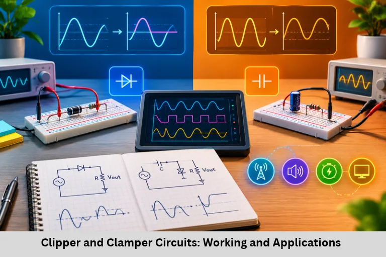
Learn clipper and clamper circuits, diode configurations, waveform shaping, voltage clamping, design calculations, troubleshooting, and embedded applications. Embedded Tech Development Academy (ETDA).
- Clipper and Clamper Circuits: Working and Applications
-
Clipper and Clamper Circuits: Mastering Waveform Shaping
- Introduction to Waveform Modification Circuits
- Clipper Circuits: Working Principle and Types
- Clamper Circuits: DC Restoration and Voltage Shifting
- Clipper vs Clamper Circuits: Key Differences
- Design Considerations and Practical Implementation
- Applications in Embedded Systems and Signal Processing
-
Frequently Asked Questions
- What is the main difference between a clipper and a clamper circuit?
- Which components are used in a clipper circuit?
- Why is a capacitor required in a clamper circuit?
- What is the role of a biased clipper?
- How does the RC time constant affect clamper performance?
- Where are clipper and clamper circuits used in embedded electronics?
- Conclusion
Clipper and Clamper Circuits: Mastering Waveform Shaping
Introduction to Waveform Modification Circuits
Clipper and clamper circuits are fundamental analog electronic circuits used to modify voltage waveforms for signal conditioning, voltage protection, and electronic signal processing. These circuits commonly use diodes, resistors, capacitors, and reference voltage sources to control the amplitude or DC level of an input signal. They are important in communication systems, power electronics, instrumentation, and embedded hardware design.
A clipper circuit limits selected portions of an input waveform without intentionally shifting the remaining waveform’s DC reference. A clamper circuit shifts the waveform upward or downward by adding a DC component while ideally preserving its peak-to-peak amplitude. Understanding diode clipping, voltage clamping, biasing, RC time constants, and waveform analysis helps engineers design reliable analog interfaces.
These techniques are useful for ADC input protection, transient suppression, pulse shaping, noise limiting, and DC restoration. For students exploring analog electronics and embedded systems, practical knowledge of waveform shaping supports sensor interfacing, circuit debugging, and hardware development. Embedded Tech Development Academy (ETDA) helps learners build technical foundations in embedded electronics. Students considering a Top Embedded Training Institute in Bangalore can explore Embedded Tech Development Academy (ETDA)‘s practical training approach and assured placement support.
Clipper Circuits: Working Principle and Types
What Is a Clipper Circuit?
A clipper, also called a voltage limiter, is a nonlinear circuit that removes or limits a selected portion of an input signal when its voltage crosses a specified threshold. The remaining waveform is passed through the circuit, subject to diode drops and component characteristics.
Basic Types of Clipper Circuits
Series Clippers
A series clipper places a diode in series with the load. Depending on the diode’s orientation, it conducts during one input polarity and blocks during the other. Positive and negative series clippers therefore suppress different portions of an AC waveform.
Parallel Clippers
A parallel clipper connects a diode in a shunt path with the load. When the diode conducts, it diverts current and limits the output voltage. The orientation of the diode determines whether positive or negative peaks are clipped.
Biased and Dual Clippers
A biased clipper uses a reference voltage to set a clipping threshold beyond the diode’s natural forward voltage. A dual clipper limits both positive and negative excursions using appropriately arranged diodes and reference sources.
Diode Clipper Operation and Threshold Calculation
For an idealized positive limiter with a reference voltage (V_{ref}) and a forward-biased diode drop (V_D), the clipping threshold is approximately:
[
V_{clip}=V_{ref}+V_D
]
The output depends on the circuit’s actual diode orientation and topology. In a limiter that passes signals below the positive threshold and clips higher voltages, an approximate transfer relationship is:
[
V_{out}=
\begin{cases}
V_{in}, & V_{in}<V_{clip}\
V_{clip}, & V_{in}\geq V_{clip}
\end{cases}
]
This is an idealized model. Real circuits exhibit load-dependent behaviour, finite diode resistance, and switching transients.
Example: Bidirectional Noise Spike Limiter
A simple limiter can use two oppositely oriented silicon diodes, a series resistor, and a signal output node. With suitable connections to ground, the diodes begin conducting when the voltage exceeds approximately +0.7 V or falls below −0.7 V.
A 1 kΩ resistor can limit current, but its suitability must be verified using the maximum input voltage, diode current rating, and resistor power rating. This circuit can reduce small voltage spikes, although it is not a precision limiter.
Clamper Circuits: DC Restoration and Voltage Shifting
What Is a Clamper Circuit?
A clamper, also known as a DC restorer, shifts an entire waveform to a different DC level. It typically contains a diode, capacitor, and resistor. Unlike a clipper, a clamper ideally preserves the waveform’s peak-to-peak amplitude while changing its position relative to the zero-voltage reference.
Types of Clamper Circuits
Positive Clamper
A positive clamper shifts the waveform upward so that its negative peaks are held near the reference level. During the appropriate input half-cycle, the diode conducts and charges the capacitor. During the remaining cycle, the stored capacitor voltage adds to the input signal.
Negative Clamper
A negative clamper shifts the waveform downward, bringing its positive peaks near the reference level. With suitable diode orientation, the capacitor charges during one half-cycle and produces a negative DC shift during subsequent cycles.
For an ideal negative clamper with a sinusoidal input of peak amplitude (V_P), the output can approach a range from (-2V_P) to 0 V. A real diode’s forward voltage reduces the shift.
Biased Clamper
A biased clamper includes an external DC reference source. It allows the waveform to be positioned around a selected voltage rather than being clamped directly to ground. Such circuits are useful when signals must remain within a defined voltage range.
RC Time Constant and Frequency Response
The capacitor must retain sufficient charge between waveform transitions. The time constant is:
[
\tau=RC
]
For effective clamping, the RC time constant is generally designed to be much larger than the input signal period, while still allowing the circuit to recover appropriately from changes in operating conditions.
Example: Video Synchronization Signal
A clamper can restore the DC reference of a video waveform so that synchronization pulses align with a specified voltage. A 0.1 µF capacitor and 1 MΩ resistor give an RC time constant of 0.1 seconds. The diode orientation, signal frequency, and loading must be considered to confirm suitability for a particular video signal.
Clipper vs Clamper Circuits: Key Differences
| Feature | Clipper Circuit | Clamper Circuit |
|---|---|---|
| Main function | Limits waveform amplitude | Shifts the DC level |
| Typical components | Diode and resistor | Diode, capacitor and resistor |
| Waveform effect | Selected peaks are removed or limited | Waveform shifts vertically |
| Peak-to-peak amplitude | Usually reduced when clipping occurs | Ideally preserved |
| Common application | Voltage limiting | DC restoration |
Design Considerations and Practical Implementation
Component Selection
Diode selection depends on forward voltage, reverse-voltage rating, leakage current, switching speed, and power dissipation. Small-signal diodes such as the 1N4148 are useful in many low-current signal circuits. Capacitor selection for clampers depends on capacitance, leakage, voltage rating, and the required RC time constant.
Zener and Precision Clippers
A Zener limiter uses a Zener diode operating in reverse breakdown to establish a voltage threshold. A series resistor limits current, and the designer must verify diode power dissipation and worst-case operating conditions.
For more accurate clipping, an operational-amplifier-based precision limiter can reduce errors caused by ordinary diode forward voltage. Its bandwidth, output swing, supply rails, and stability must be considered.
Simulation and Troubleshooting
Using LTspice or MATLAB
Circuit simulation helps engineers compare input and output waveforms, observe diode conduction, and evaluate threshold voltages. An LTspice diode model can be used to simulate a limiter, while MATLAB can illustrate the vertical shift produced by a clamper.
Common Faults and Solutions
Incorrect clipping level: Check diode orientation, reference voltage, and forward voltage.
Waveform tilt in a clamper: Increase the RC time constant when appropriate.
DC level drift: Inspect capacitor leakage and circuit loading.
Slow response: Check diode switching characteristics and parasitic capacitance.
Applications in Embedded Systems and Signal Processing
Communication, Power Electronics and Instrumentation
Clipper circuits limit unwanted voltage excursions in signal interfaces, while clampers restore DC levels in selected pulse and video-processing circuits. Related protection networks can help protect sensitive inputs when correctly designed.
In embedded systems, waveform shaping is useful in sensor interfaces, analog front ends, digital pulse conditioning, and ADC signal preparation. However, a basic diode clipper alone does not guarantee safe ADC operation; designers must verify the microcontroller’s input-voltage limits and use suitable protection components.
Embedded Tech Development Academy (ETDA) offers an opportunity for learners to explore electronics and embedded systems concepts through technical training. Those researching a Top Embedded Training Institute in Bangalore can consider practical learning opportunities and assured placement support while developing relevant engineering skills.
Frequently Asked Questions
What is the main difference between a clipper and a clamper circuit?
A clipper limits selected portions of a waveform, whereas a clamper shifts the waveform’s DC level while ideally preserving its peak-to-peak amplitude.
Which components are used in a clipper circuit?
A basic clipper commonly uses one or more diodes and resistors. Biased and dual clippers may also use DC reference sources.
Why is a capacitor required in a clamper circuit?
The capacitor stores charge during part of the input cycle. Its voltage combines with the input waveform to create the required DC shift.
What is the role of a biased clipper?
A biased clipper uses a reference voltage to set a clipping threshold above or below the natural diode conduction level.
How does the RC time constant affect clamper performance?
A sufficiently large RC time constant helps the capacitor retain charge between cycles, reducing unwanted waveform tilt. The appropriate value depends on signal frequency and loading.
Where are clipper and clamper circuits used in embedded electronics?
They can be used in signal conditioning, pulse shaping, voltage limiting, and DC restoration. Practical designs must account for ADC input limits, component ratings, signal frequency, and transient conditions.
Conclusion
Clipper and clamper circuits provide two distinct methods of waveform modification. Clippers limit selected voltage excursions, making them useful for signal limiting and voltage protection. Clampers shift the DC reference of a waveform, supporting DC restoration and pulse-processing applications. Their behaviour depends on diode characteristics, component values, input frequency, loading, and circuit topology.
A strong understanding of diode conduction, clipping thresholds, capacitor charging, RC time constants, and practical circuit simulation helps engineers design more reliable analog interfaces. These concepts are particularly valuable in embedded hardware, communication electronics, instrumentation, and signal conditioning.
Embedded Tech Development Academy (ETDA) is an option for students who want to strengthen their embedded electronics knowledge through practical technical learning. Learners seeking a Top Embedded Training Institute in Bangalore can explore Embedded Tech Development Academy (ETDA)‘s training approach and assured placement support as part of their career preparation.
Author: ETDA Trainers
Experience: 10+ Years of Industry Experience in Embedded Systems, IoT, and Embedded C Programming