
DAC Programming in LPC1768 Using Embedded C
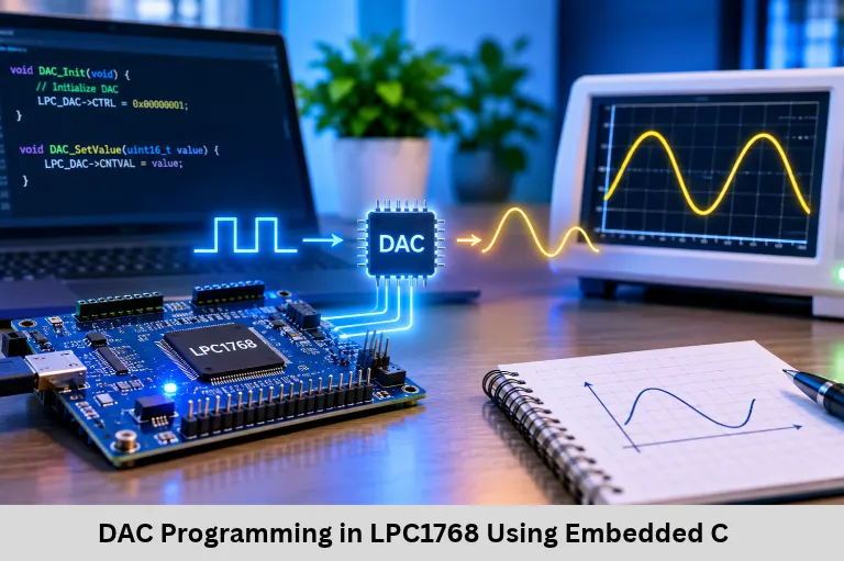
Learn DAC programming in LPC1768 using Embedded C, DAC registers, output voltage calculation, waveform generation, and practical embedded applications. Embedded Tech Development Academy (ETDA).
- DAC Programming in LPC1768 Using Embedded C
-
DAC Programming in LPC1768: Digital-to-Analog Conversion
- Introduction
- What Is a Digital-to-Analog Converter?
- LPC1768 DAC Architecture and Features
- DAC Programming in LPC1768 Using Embedded C
- Generating Analog Waveforms Using LPC1768 DAC
- Practical Applications of LPC1768 DAC Programming
- Learn Embedded C and LPC1768 Programming at ETDA
- Frequently Asked Questions
- Conclusion
DAC Programming in LPC1768: Digital-to-Analog Conversion
Introduction
Digital-to-Analog Conversion (DAC) is an important technique in embedded Systems that converts digital values generated by a microcontroller into corresponding analog voltage signals. DACs are commonly used in audio generation, waveform synthesis, signal conditioning, control systems, and instrumentation. Understanding DAC programming helps embedded developers connect digital processing with analog hardware.
The LPC1768 microcontroller, based on the ARM Cortex-M3 architecture, includes an integrated 10-bit DAC that can generate programmable analog output voltage. Learning DAC programming in LPC1768 is valuable for engineering students because it introduces register configuration, analog output control, waveform generation, and peripheral programming using Embedded C.
Students searching for a Top Embedded Training Institute in Bangalore can develop these technical skills at Embedded Tech Development Academy (ETDA), where practical microcontroller training, Embedded Systems projects, Internet of Things (IoT) development, and assured placement support help students prepare for engineering careers.
What Is a Digital-to-Analog Converter?
A Digital-to-Analog Converter converts a binary digital value into an analog voltage or current proportional to the input value. Digital systems process information using binary numbers, whereas many physical devices require continuous electrical signals for operation.
For example, a digital controller may calculate a reference voltage for a motor controller, audio circuit, or analog instrumentation system. The DAC converts that calculated digital value into an analog signal that can be used by an external circuit.
Resolution of a DAC
DAC resolution determines the number of discrete output levels available. A 10-bit DAC provides 1024 possible digital codes, ranging from 0 to 1023.
The approximate output voltage can be calculated using:
[
V_{OUT}=\frac{D}{1024}\times V_{REF}
]
Here, D represents the digital input value and VREF represents the reference voltage.
Example of DAC Output Calculation
If the LPC1768 DAC uses a 3.3 V reference and the digital input is 512, the output voltage is approximately 1.65 V.
Similarly, a digital value of 256 produces approximately 0.825 V. Increasing the digital value increases the output voltage proportionally, allowing firmware to generate different analog levels.
LPC1768 DAC Architecture and Features
The LPC1768 is a 32-bit ARM Cortex-M3 microcontroller containing several integrated peripherals for embedded development. Its DAC provides 10-bit resolution, buffered analog output, selectable settling time, and support for timer-controlled and DMA-assisted operation. <Cite refs={[“turn479678search18″,”turn479678search2”]}/>
Important DAC Registers
The primary DAC registers are:
| Register | Function |
|---|---|
| DACR | Stores the digital conversion value and bias configuration |
| DACCTRL | Controls DAC timer and DMA-related operation |
| DACNTVAL | Contains DAC counter-related information |
For basic DAC programming, the DACR register and correct pin configuration are sufficient. Advanced waveform generation can use timer and DMA features to reduce CPU involvement.
DACR Register Configuration
The DACR register contains a 10-bit VALUE field in bits 15:6 and a BIAS bit at bit 16. The VALUE field specifies the digital sample, while BIAS selects the DAC settling-time and output-current configuration.
DAC Output Pin Selection
The DAC output is available through P0.26, which also supports alternate functions such as AD0.3 and RXD3. To activate the analog output, PINSEL1 bits 21:20 must be configured to select the AOUT function. <Cite refs={[“turn479678search0″,”turn479678search20”]}/>
DAC Programming in LPC1768 Using Embedded C
DAC programming involves configuring the output pin, generating a digital sample, and writing the sample into the DAC register. The following example demonstrates basic initialization and output voltage control using LPC17xx CMSIS register definitions.
DAC Initialization
The initialization function selects the DAC alternate function on P0.26. The DAC output can then be controlled by writing digital values into the DACR register.
Embedded C Program
#include "LPC17xx.h"

void DAC_Init(void)
{
    LPC_PINCON->PINSEL1 &= ~(3U << 20);
    LPC_PINCON->PINSEL1 |=  (2U << 20);
}

void DAC_SetValue(unsigned int value)
{
    value &= 0x3FFU;
    LPC_DAC->DACR = (value << 6);
}

int main(void)
{
    DAC_Init();

    while(1)
    {
        DAC_SetValue(512);
    }
}
Program Explanation
The DAC_Init() function configures P0.26 for analog output instead of its default GPIO functionality. The DAC_SetValue() function limits the input to ten bits and shifts the digital sample into the correct DACR register position.
The main program continuously writes 512, producing an approximately constant analog voltage of 1.65 V when the reference voltage is 3.3 V. The actual output should be measured using an oscilloscope or suitable voltmeter.
Generating Analog Waveforms Using LPC1768 DAC
The DAC can generate changing voltage levels by continuously updating its digital input. This technique is useful for producing staircase signals, sawtooth waveforms, and approximated sine waves.
Sawtooth Waveform Generation
A sawtooth waveform can be generated by gradually increasing the digital sample from 0 to 1023. After reaching the maximum code, the program resets the value to zero and repeats the sequence.
unsigned int sample;

while(1)
{
    for(sample = 0; sample < 1024; sample++)
    {
        DAC_SetValue(sample);
    }
}
The output resembles a staircase ramp because the DAC produces discrete voltage levels. Adding a controlled delay between updates changes the waveform frequency, while a smaller increment produces finer visible steps.
Improving Waveform Accuracy
For stable waveform generation, developers should use hardware timers to determine the sample update interval. Timer interrupts provide predictable timing, while DMA can transfer samples with reduced CPU overhead.
For audio and signal-generation applications, waveform samples can be stored in lookup tables and transmitted repeatedly to the DAC. The achievable frequency and quality depend on sample rate, settling time, load conditions, and waveform resolution.
Practical Applications of LPC1768 DAC Programming
DAC programming is useful in several Embedded Systems applications. Students can develop programmable voltage sources, audio signal generators, sensor calibration circuits, analog control interfaces, and waveform generation projects.
In Internet of Things (IoT) applications, DAC output can support analog actuator control or reference-signal generation when the connected hardware requires an analog voltage. However, the DAC should not directly drive high-current loads; suitable external amplifiers or driver circuits are required.
Learn Embedded C and LPC1768 Programming at ETDA
Embedded Tech Development Academy (ETDA) helps engineering students develop practical knowledge of Embedded C, ARM Cortex-M programming, and microcontroller peripheral interfacing. DAC programming provides valuable experience in register-level configuration, digital signal generation, and analog hardware interaction.
Students can progress through GPIO programming, ADC and DAC interfacing, UART, SPI, I2C, timers, interrupts, RTOS, and Internet of Things (IoT) projects. These technical skills help learners understand how microcontroller peripherals operate within real embedded applications.
Students evaluating a Top Embedded Training Institute in Bangalore should consider hands-on laboratory experience, curriculum depth, technical mentoring, and project opportunities. Embedded Tech Development Academy (ETDA) combines practical training with assured placement support to help students prepare for embedded engineering roles.
Frequently Asked Questions
What is the DAC resolution of LPC1768?
The LPC1768 contains a 10-bit DAC that provides 1024 digital output levels, from 0 to 1023.
Which pin is used for DAC output in LPC1768?
P0.26 is used for analog output when its alternate function is configured as AOUT.
What is the purpose of the DACR register?
DACR contains the digital conversion value in bits 15:6 and the BIAS configuration bit at bit 16.
Can LPC1768 generate a sine wave using its DAC?
Yes. A sine-wave lookup table can provide digital samples that are repeatedly written to the DAC at controlled intervals.
What is the difference between ADC and DAC?
ADC converts analog signals into digital values, whereas DAC converts digital values into analog voltage signals.
Why should embedded engineering students learn DAC programming?
DAC programming develops practical skills in register configuration, analog interfacing, waveform generation, and microcontroller peripheral programming.
Conclusion
DAC programming in LPC1768 demonstrates how digital information can be converted into useful analog voltage signals. Understanding the DACR register, output pin selection, digital sample calculation, and waveform generation helps students develop practical microcontroller programming skills.
These concepts are valuable for Embedded Systems, signal processing, automation, and Internet of Things (IoT) applications. Students searching for a Top Embedded Training Institute in Bangalore can strengthen their technical foundation at Embedded Tech Development Academy (ETDA) through practical ARM programming, peripheral interfacing, real-world projects, and assured placement support.
Author: ETDA Trainers
Experience: 10+ Years of Industry Experience in Embedded Systems, IoT, and Embedded C Programming