
Ethernet Interfacing with LPC1768 ARM Cortex-M3
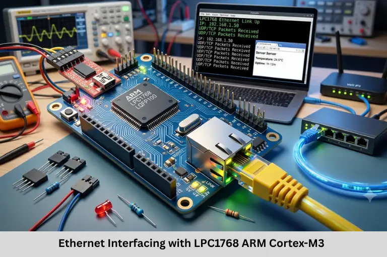
Learn Ethernet interfacing with LPC1768, including PHY configuration, RMII signals, MAC initialization, DMA descriptors, lwIP integration, and network testing. Embedded Tech Development Academy (ETDA).
- Ethernet Interfacing with LPC1768 ARM Cortex-M3
-
Interfacing Ethernet with ARM Cortex-M3 Processor-Based LPC1768 Controller
- Introduction to Ethernet Interfacing with LPC1768
- 1. Understanding the LPC1768 Ethernet Controller
- 2. Hardware Requirements and Connections
- 3. MII vs. RMII Interface
- Configuring Ethernet Pins in LPC1768
- 5. Initializing the Ethernet MAC
- 6. Initializing and Communicating with the PHY
- 7. Integrating a TCP/IP Stack
- 8. Testing and Troubleshooting Ethernet
- 9. Applications of Ethernet on LPC1768
- Frequently Asked Questions
- Conclusion
Interfacing Ethernet with ARM Cortex-M3 Processor-Based LPC1768 Controller
Introduction to Ethernet Interfacing with LPC1768
Ethernet is a widely used wired networking technology in embedded systems because it provides reliable communication between microcontrollers, computers, industrial controllers, and network servers. The NXP LPC1768, based on the ARM Cortex-M3 processor, integrates a 10/100 Mbps Ethernet Media Access Controller (MAC), making it suitable for network-connected applications such as industrial automation, Internet of Things (IoT) gateways, remote monitoring, smart metering, and data acquisition systems.
However, the LPC1768 requires an external Ethernet Physical Layer (PHY) transceiver to connect its MAC to the physical Ethernet network. Engineers must configure the MAC and PHY, select the appropriate MII or RMII interface, establish the reference clock, manage transmit and receive buffers, and integrate a TCP/IP stack to support protocols such as IP, TCP, UDP, HTTP, and MQTT.
Understanding Ethernet interfacing with LPC1768 also introduces important embedded networking concepts, including MAC addressing, DMA descriptors, PHY register access through MDIO/MDC, IP configuration, and packet debugging with Wireshark. At Embedded Tech Development Academy (ETDA), practical embedded systems learning can help students connect ARM microcontroller programming with real-world networking applications. Learners exploring the Top Embedded Training Institute in Bangalore can focus on hands-on firmware development and communication protocols, while assured placement support can help them prepare for embedded software and firmware development opportunities.
1. Understanding the LPC1768 Ethernet Controller
The LPC1768 integrates an Ethernet MAC designed for IEEE 802.3-compatible networking. The MAC manages Ethernet frames, while the external PHY handles electrical signaling and the physical network interface.
Key Ethernet Features
- 10 Mbps and 100 Mbps Ethernet operation, depending on link negotiation and configuration.
- Media Independent Interface (MII) and Reduced Media Independent Interface (RMII) support.
- Transmit and receive DMA mechanisms.
- Ethernet frame filtering and MAC-address handling.
- PHY management through the MDC and MDIO signals.
- Support for integration with embedded TCP/IP stacks.
Why Is an External PHY Required?
The MAC processes Ethernet frames, but it does not directly drive the cable-side electrical signals. An external PHY converts data between the MAC interface and the physical Ethernet link. Compatible PHY selection depends on the LPC1768 interface mode, voltage requirements, clock architecture, and board design.
2. Hardware Requirements and Connections
Essential Components
A typical Ethernet project requires an LPC1768 development board, a compatible PHY such as the DP83848, an RJ45 connector with suitable magnetics, a stable power supply, decoupling capacitors, and an Ethernet cable. Other PHYs may be usable when their interface and clock requirements match the design.
Important RMII Signals
| Signal | Function |
|---|---|
| TXD0, TXD1 | Transmit data |
| TXEN | Enables transmission |
| RXD0, RXD1 | Receive data |
| CRS_DV | Indicates receive activity and data validity |
| REF_CLK | 50 MHz reference clock |
| MDC, MDIO | PHY management clock and data |
Connecting the PHY to the Network
Connect the LPC1768 MAC signals to the corresponding PHY pins according to the datasheets and board schematic. The PHY connects to the RJ45 interface through Ethernet magnetics, which provide isolation and help meet interface requirements.
Clock, Power, and PCB Layout
RMII normally uses a 50 MHz reference clock. The clock may be generated or supplied by the PHY or another clock source, depending on the design. Follow the selected PHY datasheet for clock input, crystal, and oscillator requirements rather than assuming a 50 MHz crystal is always required. Keep high-speed signal routing controlled, provide local decoupling, and place ESD protection appropriately.
3. MII vs. RMII Interface
Media Independent Interface (MII)
MII uses separate transmit and receive data paths, generally with four data bits per direction and additional control and clock signals. It requires more signal connections but is supported by many Ethernet MACs and PHYs.
Reduced Media Independent Interface (RMII)
RMII uses two transmit and two receive data bits, reducing the number of signal connections. It uses a shared 50 MHz reference clock, which simplifies pin usage but requires correct clock synchronization.
For many LPC1768 development boards, RMII is a practical choice because it reduces routing complexity. The exact mode must match the board’s PHY wiring and controller configuration.
Configuring Ethernet Pins in LPC1768
Pin Multiplexing
The LPC1768 uses pin-function selection registers to assign physical pins to Ethernet functions. Configure all required signals, including transmit, receive, clock, and management lines, using the exact function selections specified in the LPC1768 datasheet.
Illustrative pseudocode:
/* Conceptual initialization sequence */
configure_ethernet_pin_functions();
configure_rmii_clock_source();
enable_ethernet_peripheral_power();
The exact PINSEL register settings vary by pin and function. Avoid copying generic bit shifts without checking the pin-function tables. Incorrect pin multiplexing can prevent PHY communication even when the firmware appears to initialize successfully.
5. Initializing the Ethernet MAC
Step 1: Enable and Reset the MAC
Enable the Ethernet peripheral and perform the documented reset sequence. Wait for reset completion before configuring MAC registers.
Step 2: Configure MAC Operation
Configure transmit and receive operation, frame filtering, duplex mode, and speed settings. When auto-negotiation is used, ensure the MAC configuration matches the link parameters reported by the PHY.
Step 3: Configure the MAC Address
Each network interface needs a valid, unique MAC address. Use an address legitimately assigned to the device or a locally administered address appropriate for the deployment. A MAC address is not an IP address; it identifies the interface at the Ethernet layer.
Step 4: Configure DMA Descriptors
The MAC uses transmit and receive descriptors to manage packet buffers. Firmware must initialize descriptor rings or arrays, configure buffer addresses and lengths, and process completion status correctly. Ensure descriptor alignment, memory placement, ownership transitions, and buffer lifetime follow the LPC1768 documentation and selected driver.
6. Initializing and Communicating with the PHY
PHY Register Access
The LPC1768 communicates with the PHY through the MDC clock and MDIO data signals. Read the PHY identifier registers to verify that the management interface works. Then configure auto-negotiation and supported speed and duplex options as required.
Checking Link Status
Read the PHY status registers to determine whether a physical link is established and whether negotiation has completed. Check the cable, switch port, clock, reset pin, power supply, and PHY configuration if the link remains down.
7. Integrating a TCP/IP Stack
The Ethernet MAC transmits and receives frames but does not independently provide high-level networking protocols. A TCP/IP stack implements functions such as IP addressing, ARP, ICMP, TCP, and UDP.
Using lwIP
lwIP is a lightweight TCP/IP stack suitable for many resource-constrained embedded systems. Other options may include uIP, vendor-provided middleware, or an RTOS-integrated networking stack when compatible with the platform.
Configure the Ethernet driver, packet buffers, network interface, and IP settings before starting communication.
Illustrative static IPv4 configuration:
IP4_ADDR(&ipaddr, 192, 168, 1, 100);
IP4_ADDR(&netmask, 255, 255, 255, 0);
IP4_ADDR(&gw, 192, 168, 1, 1);
These example addresses must be adapted to the actual network. DHCP may be used instead of static configuration when supported by the application.
8. Testing and Troubleshooting Ethernet
Basic Network Tests
- Check link status: Confirm that the PHY reports an active link.
- Ping the device: From a PC on the same network, run
ping 192.168.1.100if that address has been configured and ICMP is enabled. - Test TCP or UDP: Run a simple server or client and verify the packets.
- Capture packets: Use Wireshark to inspect ARP, ICMP, TCP, or UDP traffic.
- Test an HTTP server: If implemented, open
http://192.168.1.100/from a compatible device on the same network.
Common causes of failure include incorrect clock configuration, invalid pin multiplexing, mismatched MAC and PHY speed settings, descriptor errors, incorrect IP addressing, and firewall restrictions.
9. Applications of Ethernet on LPC1768
Ethernet connectivity enables industrial automation controllers, Internet of Things (IoT) gateways, remote monitoring equipment, smart meters, data loggers, web-based configuration tools, and SCADA-connected systems. Practical projects combine Embedded C, ARM Cortex-M3 programming, Ethernet hardware, TCP/IP networking, and systematic debugging.
Embedded Tech Development Academy (ETDA) can help learners build foundational knowledge in embedded firmware and networking. Those comparing the Top Embedded Training Institute in Bangalore should look for hands-on work with microcontrollers, communication interfaces, and network debugging. Embedded Tech Development Academy (ETDA)‘s assured placement support can help learners prepare for opportunities in embedded software and firmware development.
Frequently Asked Questions
Does the LPC1768 have a built-in Ethernet controller?
Yes. The LPC1768 includes an Ethernet MAC, but it requires a compatible external PHY to connect to a physical Ethernet network.
What is the difference between MII and RMII?
MII uses more data and control connections, while RMII reduces the signal count by using two-bit transmit and receive data paths and a 50 MHz reference clock.
Why is a PHY required for Ethernet interfacing?
The PHY converts MAC-level data into physical-layer signaling and receives signals from the Ethernet link. It also manages functions such as link establishment and speed negotiation.
Which TCP/IP stack can be used with the LPC1768?
lwIP is a common lightweight option. The selected stack must be compatible with the hardware, compiler, memory limits, and any RTOS used by the project.
How can Ethernet communication be tested on the LPC1768?
Check PHY link status, verify IP configuration, ping the device where supported, test TCP or UDP communication, and inspect network packets using Wireshark.
Conclusion
Interfacing Ethernet with the LPC1768 ARM Cortex-M3 controller requires coordinated hardware and firmware design. Developers must select a compatible PHY, configure MII or RMII signals, provide a correct reference clock, initialize the MAC, set up DMA descriptors, and integrate a suitable TCP/IP stack. Reliable Ethernet communication also depends on valid MAC and IP addresses, correct link negotiation, PCB signal integrity, and systematic testing with tools such as ping and Wireshark.
Learning these concepts provides a strong foundation in embedded networking, Internet of Things (IoT) connectivity, TCP/IP protocol integration, and network-enabled firmware development. Embedded Tech Development Academy (ETDA) supports practical embedded technology learning, while learners evaluating the Top Embedded Training Institute in Bangalore can prioritize real hardware projects and network troubleshooting experience. With assured placement support, Embedded Tech Development Academy (ETDA) aims to help aspiring engineers work toward careers involving ARM microcontrollers, embedded networking, and connected-device development.
Author: ETDA Trainers
Experience: 10+ Years of Industry Experience in Embedded Systems, IoT, and Embedded C Programming