
8051 Embedded C Programming for Beginners
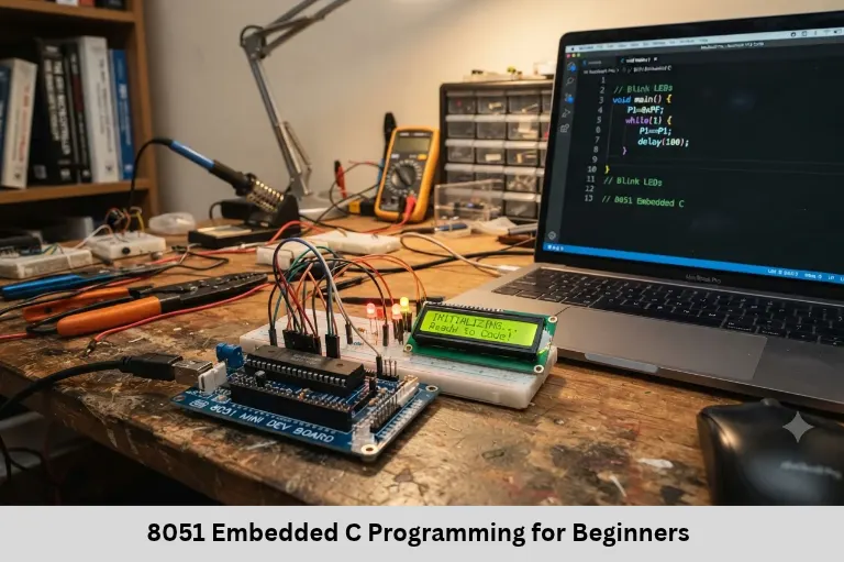
Learn how to write, compile and execute your first Embedded C program on 8051 using Keil µVision with a practical LED blinking example. Embedded Tech Development Academy (ETDA).
- 8051 Embedded C Programming for Beginners
-
How to Write and Execute Your First Embedded C Program on 8051
- Introduction
- Understanding the 8051 Microcontroller
- Tools Required for Your First 8051 Embedded C Program
- Writing Your First Embedded C Program on 8051
- Compiling and Executing the Program
- Common Errors in 8051 Embedded C Programming
- Advancing Your 8051 Programming Skills with ETDA
- Frequently Asked Questions
- Conclusion
How to Write and Execute Your First Embedded C Program on 8051
Introduction
Learning Embedded C programming is an important step for students who want to build a career in embedded systems, firmware development, and microcontroller-based applications. The 8051 microcontroller is one of the best platforms for beginners because it helps them understand how software interacts directly with hardware. Writing and executing your first Embedded C program on 8051 provides practical knowledge of registers, input/output ports, and basic hardware control.
For students searching for practical embedded systems training, understanding 8051 programming creates a strong technical foundation. The Top Embedded Training Institute in Bangalore approach should combine programming concepts with real-time hardware experiments. At Embedded Tech Development Academy (ETDA), students learn microcontroller programming through practical sessions, project development, and industry-oriented training, along with assured placement support to prepare for embedded engineering opportunities.
Understanding the 8051 Microcontroller
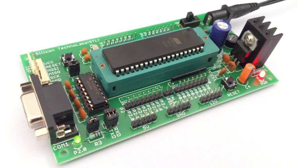
The 8051 is an 8-bit microcontroller widely used in educational projects and basic embedded applications. It combines a CPU, memory, timers, serial communication, and digital input/output ports in a single chip.
Its four 8-bit ports provide 32 general-purpose input/output pins. These pins allow developers to connect LEDs, switches, sensors, displays, and other electronic components.
Important Features of the 8051
8-bit CPU architecture.
4 KB internal program memory in the classic 8051.
128 bytes of internal RAM in the standard 8051.
Four 8-bit I/O ports.
Two 16-bit timers/counters.
Full-duplex serial communication.
Five interrupt sources in the classic architecture.
Understanding these features helps beginners learn how a microcontroller processes instructions and controls external devices.
Tools Required for Your First 8051 Embedded C Program
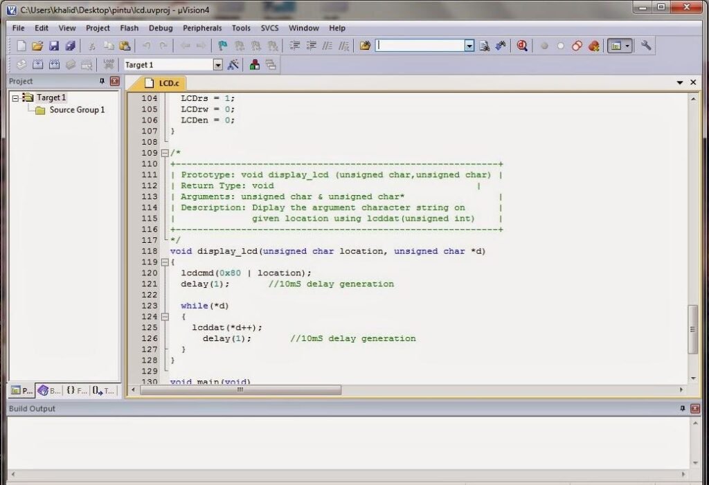
Before writing the program, you need a development environment and basic hardware components. These tools help you write, compile, test, and execute your first application.
Keil µVision IDE
Keil µVision is a commonly used development environment for writing, compiling, and debugging Embedded C programs for compatible 8051 devices. It provides a code editor, compiler, project configuration, and debugging facilities.
8051 Development Board
An 8051 development board allows you to execute your program on actual hardware. It generally includes the microcontroller, power supply connections, reset circuit, and accessible I/O pins.
Programming Interface
Depending on the development board, you may need a compatible programmer or interface to transfer the generated HEX file into the microcontroller.
LED and Resistor
An LED is a simple output device for testing your first program. A suitable current-limiting resistor protects the LED and microcontroller output from excessive current.
Writing Your First Embedded C Program on 8051
A beginner-friendly project is LED blinking. This program repeatedly switches an output pin between logic HIGH and logic LOW, making the connected LED turn ON and OFF.
Step 1 – Create a New Project
Open Keil µVision and select Project → New µVision Project. Choose a project name and save it in a suitable folder. Select the correct 8051 device from the device database based on the microcontroller used by your development board.
Step 2 – Add an Embedded C Source File
Create a new source file and save it with the .c extension. Add the appropriate header file for the selected 8051 toolchain. The header file provides register definitions required to access the microcontroller peripherals.
Step 3 – Write the LED Blinking Program
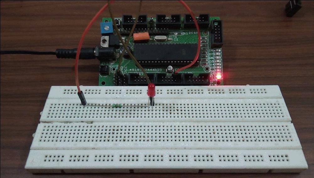
The following example uses Port 1, Pin 0 (P1.0), as an LED output. It assumes an active-HIGH LED connection and uses a software delay.
#include <REG51.H>

sbit LED = P1^0;

void delay(void)
{
    unsigned int i, j;

    for(i = 0; i < 500; i++)
    {
        for(j = 0; j < 1275; j++)
        {
            ;
        }
    }
}

void main(void)
{
    while(1)
    {
        LED = 1;
        delay();

        LED = 0;
        delay();
    }
}
Step 4 – Understand the Program
Each instruction performs a specific operation in the microcontroller.
#include <REG51.H>provides register definitions for the classic 8051 in the Keil C51 environment.sbit LED = P1^0assigns a meaningful name to the P1.0 bit.delay()creates a software delay using nested loops.LED = 1sets the output pin HIGH.LED = 0sets the output pin LOW.while(1)continuously repeats the LED operation.
How Does the LED Blinking Logic Work?
tWhen the program starts, the microcontroller executes the instructions inside the infinite loop. First, P1.0 becomes HIGH, turning ON the LED in an active-HIGH circuit. The delay function keeps the output in that state temporarily.
After the delay, P1.0 becomes LOW, switching OFF the LED. This process repeats continuously, creating the blinking effect.
Understanding Software Delay in 8051
The nested loops generate a basic software delay by making the processor execute repeated instructions. However, the actual delay depends on the oscillator frequency, compiler optimization, and instruction execution time.
For applications that require accurate timing, hardware timers such as Timer 0 and Timer 1 are more suitable than software delay loops.
Compiling and Executing the Program
After writing the source code, you need to compile the project and transfer the generated program to the microcontroller.
Step 5 – Build the Project
Click the Build option in Keil µVision. The compiler checks the program for syntax errors and generates the required output files. If compilation is successful, the build output should show zero errors.
Enable HEX file generation in the project output settings if you need an Intel HEX file for hardware programming.
Step 6 – Load the Program into the 8051
Connect the development board to the computer using its supported programming interface. Use the appropriate programming utility to transfer the generated HEX file into the microcontroller.
Step 7 – Test the Output
Power the development board and observe the LED connected to P1.0. It should repeatedly switch ON and OFF.
If the LED does not blink, check the port connection, power supply, oscillator, reset circuit, programmer configuration, and LED polarity.
Common Errors in 8051 Embedded C Programming
Beginners may face several issues while writing and executing their first program. Understanding these errors makes debugging easier.
1. Header File Errors
Using an incorrect device header file can cause register-definition errors. Always select the header supported by your compiler and target microcontroller.
2. Incorrect Port Connections
Connecting an LED to a different port pin than the one defined in the program will prevent the expected output. Verify the circuit connections before testing.
3. Compilation Errors
Missing semicolons, incorrect variable declarations, and spelling mistakes can cause compilation failures. Read compiler messages carefully and correct the reported errors.
4. Programming and Hardware Issues
A successful compilation does not automatically mean that the program has been loaded into the microcontroller. Check the programming interface and verify that the correct HEX file has been selected.
Advancing Your 8051 Programming Skills with ETDA
Writing an LED blinking program is only the beginning of microcontroller programming. Students should gradually move towards more advanced experiments, such as switch interfacing, seven-segment displays, LCD programming, timer configuration, UART communication, and interrupt handling.
Practical Embedded C Training for Students
At Embedded Tech Development Academy (ETDA), students can strengthen their practical knowledge through structured Embedded C programming and microcontroller training. The learning process focuses on understanding hardware connections, writing efficient code, debugging errors, and developing working projects.
Building Industry-Ready Embedded Skills
For students looking for the Top Embedded Training Institute in Bangalore, practical exposure is important because embedded engineering requires both programming knowledge and hardware understanding. Embedded Tech Development Academy (ETDA) combines technical learning with hands-on project experience and assured placement support, helping learners prepare for technical interviews and embedded development opportunities.
Frequently Asked Questions
What is Embedded C programming in 8051?
Embedded C programming in 8051 involves writing C-language instructions to control the microcontroller’s hardware, including ports, timers, interrupts, and communication peripherals.
Which software is used for 8051 programming?
Keil µVision with the C51 compiler is commonly used to write, compile, and debug Embedded C programs for compatible 8051 microcontrollers.
What is the first project for learning 8051?
An LED blinking project is a suitable beginner project because it teaches basic output-port control and program execution.
What is the purpose of the REG51.H header file?
The REG51.H header file provides register and peripheral definitions for the classic 8051 architecture in the Keil C51 development environment.
How is an Embedded C program transferred to the 8051?
After compilation, the program can be generated as an Intel HEX file and transferred to the microcontroller using a compatible programmer or development-board programming interface.
What should students learn after the 8051 LED blinking program?
Students can progress to switch interfacing, LCD programming, timers, interrupts, UART communication, sensor interfacing, and more advanced embedded projects.
Conclusion
Writing and executing your first Embedded C program on 8051 is an excellent starting point for understanding microcontroller-based development. By creating an LED blinking application, students learn how to configure I/O pins, write C code, compile a project, generate a HEX file, and test the output on real hardware.
After mastering these fundamentals, learners can explore timers, interrupts, communication protocols, and sensor interfacing. Choosing the Top Embedded Training Institute in Bangalore can help students gain structured practical experience. Embedded Tech Development Academy (ETDA) supports this learning journey through hands-on training, real-time projects, and assured placement support, helping aspiring engineers build a foundation for careers in embedded systems and firmware development.
Author: ETDA Trainers
Experience: 10+ Years of Industry Experience in Embedded Systems, IoT, and Embedded C Programming