
LPC1768 DMA: Direct Memory Access Guide
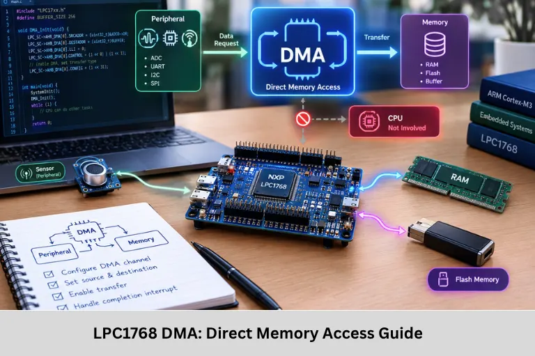
Learn LPC1768 DMA, GPDMA channels, ADC, UART, memory transfers, linked lists, interrupts, debugging and high-speed embedded data transfer. Embedded Tech Development Academy (ETDA).
- LPC1768 DMA: Direct Memory Access Guide
-
LPC1768 DMA: A Practical Guide to Direct Memory Access
- Introduction to DMA in LPC1768
- What Is DMA and Why Does It Matter?
- LPC1768 GPDMA Architecture
- Configuring DMA for ADC Data Acquisition
- UART DMA for High-Speed Communication
- Memory-to-Memory DMA Transfers
- DMA Linked-List Transfers
- DMA Interrupts and Transfer Completion
- Common DMA Pitfalls and Debugging
- DMA Performance Benefits
- DMA Applications in Embedded Systems and IoT
- Frequently Asked Questions
- Conclusion
LPC1768 DMA: A Practical Guide to Direct Memory Access
Introduction to DMA in LPC1768
In high-performance embedded systems, moving large amounts of data between peripherals and memory can consume significant CPU processing time. If the processor must continuously read every ADC sample, copy every UART byte, or move buffers between SRAM locations, valuable CPU cycles are spent performing data-transfer operations instead of executing application logic. Direct Memory Access (DMA) solves this problem by allowing dedicated hardware to transfer data between peripherals and memory with minimal CPU involvement.
The NXP LPC1768 microcontroller incorporates a General Purpose DMA (GPDMA) controller designed to handle high-speed data movement. DMA can be used for peripheral-to-memory, memory-to-peripheral, and memory-to-memory transfers. This is particularly useful for ADC acquisition, UART communication, SPI data processing, and continuous buffer movement.
Important DMA concepts include DMA channels, source and destination addresses, transfer width, burst size, peripheral request signals, transfer counters, terminal-count interrupts, DMA descriptors, linked-list items (LLI), memory alignment, buffer management, and interrupt handling.
DMA is especially valuable in real-time embedded systems because it reduces CPU overhead and helps maintain predictable data movement. It can also allow the CPU to perform control algorithms, communication management, or other processing while DMA operates in the background.
For engineers learning microcontrollers and firmware development, Embedded Tech Development Academy (ETDA) provides practical exposure to embedded C, ARM microcontrollers, peripherals, DMA, and real-time programming. Learners looking for a Top Embedded Training Institute in Bangalore can develop practical embedded systems skills with assured placement support. DMA knowledge is also valuable when developing high-throughput Internet of Things (IoT) devices that continuously acquire and process sensor data.
What Is DMA and Why Does It Matter?
Direct Memory Access Fundamentals
DMA is a hardware mechanism that transfers data without requiring the CPU to execute an instruction for every individual data element.
Conventional CPU-Based Transfer
In a CPU-driven transfer, firmware repeatedly performs operations such as:
for (int i = 0; i < 1000; i++)
    buffer[i] = ADC_VALUE;
CPU Limitation
For large or continuous transfers, this approach consumes processor cycles and can interfere with time-critical firmware.
DMA-Based Transfer
With DMA, firmware configures the source, destination, transfer size, and transfer direction. The DMA controller then performs the transfer automatically.
Peripheral
    ↓
DMA Controller
    ↓
SRAM Buffer
The CPU generally becomes involved only during configuration, completion, or error handling.
LPC1768 GPDMA Architecture
General Purpose DMA Controller
The LPC1768 provides an 8-channel GPDMA controller. Each channel can be configured independently for supported transfer operations.
Supported Transfer Types
The major transfer categories are:
- Peripheral-to-memory
- Memory-to-peripheral
- Memory-to-memory
DMA Configuration Parameters
A DMA transfer normally requires:
- Source address
- Destination address
- Transfer size
- Source transfer width
- Destination transfer width
- Source increment configuration
- Destination increment configuration
- Transfer type
- Peripheral DMA request
- Completion/error interrupt configuration
The exact peripheral request and register configuration depend on the LPC1768 peripheral and the device header or SDK being used.
Configuring DMA for ADC Data Acquisition
ADC-to-SRAM Data Transfer
ADC acquisition is a common DMA application because sensors can generate continuous samples. Instead of reading every ADC result through software, DMA can transfer ADC data into an SRAM buffer.
DMA Setup Sequence
A typical implementation follows this sequence:
- Enable required peripheral clocks and power.
- Configure the ADC.
- Allocate an SRAM buffer.
- Select a DMA channel.
- Configure the source peripheral register.
- Configure the destination SRAM address.
- Set transfer width and count.
- Configure the peripheral DMA request.
- Enable terminal-count interrupt if required.
- Start the ADC and DMA operation.
Conceptual Configuration
void configure_dma_adc(void)
{
    DMA_Channel->SRCADDR  = (uint32_t)&ADC_RESULT;
    DMA_Channel->DESTADDR = (uint32_t)adc_buffer;

    DMA_Channel->CONTROL =
        TRANSFER_COUNT(1000) |
        SRC_WIDTH_16BIT |
        DST_WIDTH_16BIT |
        SRC_FIXED |
        DST_INCREMENT |
        TERMINAL_COUNT_INT;
}
The register names shown above are conceptual; actual LPC1768 CMSIS or vendor-library definitions should be used for the selected development environment.
UART DMA for High-Speed Communication
Memory-to-UART Transfer
UART communication is another practical DMA application. Instead of the CPU writing each byte into the UART transmit register, DMA can move a complete buffer to the UART peripheral.
Transmission Flow
SRAM Buffer
    ↓
DMA Channel
    ↓
UART Transmit Register
    ↓
Serial Output
Example Configuration
void uart_dma_send(uint8_t *data, uint32_t length)
{
    DMA_Channel->SRCADDR  = (uint32_t)data;
    DMA_Channel->DESTADDR = (uint32_t)&UART1->THR;

    DMA_Channel->CONTROL =
        TRANSFER_COUNT(length) |
        SRC_INCREMENT |
        DST_FIXED |
        SRC_WIDTH_8BIT |
        DST_WIDTH_8BIT;
}
The UART peripheral must also be configured to generate the appropriate DMA request. This approach is useful for transmitting large packets without continuously polling the UART status register.
Memory-to-Memory DMA Transfers
Fast Buffer Movement
DMA can also transfer data between two memory locations. This can be useful when firmware needs to move large buffers while allowing the CPU to perform another task.
Example
void dma_memcpy(void *dest, void *src, uint32_t size)
{
    DMA_Channel->SRCADDR  = (uint32_t)src;
    DMA_Channel->DESTADDR = (uint32_t)dest;

    DMA_Channel->CONTROL =
        TRANSFER_COUNT(size) |
        SRC_INCREMENT |
        DST_INCREMENT;
}
Practical Applications
Memory-to-memory DMA can be useful for audio buffers, sensor blocks, communication packets, image data, and intermediate processing buffers.
DMA Linked-List Transfers
Linked List Items
For complex applications, a single DMA configuration may not be sufficient. The LPC1768 GPDMA supports Linked List Items (LLIs), allowing multiple DMA transfer descriptors to be chained.
LLI Structure
A typical descriptor contains source address, destination address, control information, and a pointer to the next descriptor.
typedef struct
{
    uint32_t src;
    uint32_t dest;
    uint32_t control;
    uint32_t next;
} DMA_LLI;
Chained Transfers
LLI 0 → LLI 1 → LLI 2 → LLI 3 → EndThis allows the DMA controller to process multiple buffers with limited CPU intervention.
DMA Interrupts and Transfer Completion
Terminal Count Interrupt
A DMA channel can generate an interrupt when the programmed transfer count reaches zero.
Completion Processing
The interrupt handler can:
- Identify the completed channel.
- Verify transfer status.
- Process the received buffer.
- Start another transfer.
- Signal a task or state machine.
Error Handling
DMA error interrupts should also be monitored because invalid addresses, configuration problems, or unsupported transfer conditions can result in failed transfers.
if (DMA_INT_ERROR(channel))
{
    DMA_CLEAR_ERROR(channel);
    handle_dma_error();
}
Common DMA Pitfalls and Debugging
Memory Alignment
Transfer width and address alignment must be compatible.
Buffer Placement
DMA buffers should be placed in memory regions accessible by the DMA controller.
SRAM Considerations
For LPC1768 firmware, carefully verify the selected SRAM region, linker configuration, and DMA accessibility before placing buffers.
Incorrect Peripheral Requests
DMA requires the correct hardware request source.
Peripheral Configuration
The ADC, UART, SPI, or other peripheral must be configured to generate the appropriate DMA request.
Debugging Strategy
Check the DMA channel configuration, peripheral status, transfer counter, interrupt status, source address, and destination address using a debugger.
DMA Performance Benefits
CPU Utilization
DMA reduces the number of CPU instructions required for repetitive data movement.
Throughput
The actual transfer speed depends on bus arbitration, peripheral speed, memory access, transfer width, burst configuration, and system clocking.
Practical Comparison
A CPU-based transfer may require continuous processor attention, whereas DMA allows the processor to perform other operations during the transfer. Therefore, the main advantage is not simply raw transfer speed but lower CPU overhead and improved system concurrency.
DMA Applications in Embedded Systems and IoT
Real-Time Data Acquisition
DMA is useful for continuous ADC sampling, sensor acquisition, audio capture, and instrumentation.
Communication Buffers
UART, SPI, and other supported peripherals can use DMA to handle larger communication buffers efficiently.
Internet of Things (IoT)
In Internet of Things (IoT) devices, DMA can continuously move sensor and communication data while the CPU performs filtering, protocol processing, and control algorithms.
Real-Time Processing
System Architecture
Sensor → Peripheral → DMA → SRAM
                         ↓
                       CPU
                         ↓
                 Data Processing
                         ↓
                 IoT Communication
This architecture can improve responsiveness in resource-constrained embedded systems.
Frequently Asked Questions
What is DMA in LPC1768?
DMA, or Direct Memory Access, is a hardware mechanism that transfers data between supported peripherals and memory, or between memory locations, with minimal CPU intervention.
How many DMA channels does LPC1768 have?
The LPC1768 provides eight general-purpose DMA channels, allowing multiple transfer operations to be configured according to the application’s peripheral and memory requirements.
Why is DMA useful for ADC applications?
DMA can automatically transfer ADC results into an SRAM buffer, reducing CPU overhead and making continuous or high-frequency sampling more efficient.
Can DMA be used for UART communication?
Yes. DMA can transfer data between memory and supported UART interfaces, reducing the CPU workload associated with transmitting or receiving larger data buffers.
What are DMA linked lists?
Linked List Items (LLIs) are DMA descriptors that allow multiple transfer configurations to be chained together. They are useful for repeated or complex buffer transfers with limited CPU intervention.
Conclusion
The LPC1768 DMA controller is an important hardware feature for designing efficient and responsive embedded systems. Instead of requiring the CPU to handle every data movement operation, the GPDMA controller can transfer information between supported peripherals and memory while the processor performs application-level tasks.
Understanding DMA channels, source and destination addressing, transfer widths, burst sizes, peripheral requests, SRAM buffers, terminal-count interrupts, error handling, and Linked List Items gives embedded developers the foundation required to implement efficient firmware. Applications such as ADC data acquisition, UART communication, SPI transfers, memory-to-memory copying, and continuous sensor buffering can benefit significantly from DMA.
For engineers working on real-time embedded systems, DMA is particularly useful because it improves CPU availability and allows data movement to occur concurrently with computation. In Internet of Things (IoT) devices, this can allow sensor acquisition and communication buffers to operate efficiently while the CPU performs filtering, decision-making, and protocol processing.
Embedded Tech Development Academy (ETDA) provides practical technical learning in embedded C, ARM microcontrollers, peripheral programming, DMA, communication protocols, and real-time firmware development. Learners looking for a Top Embedded Training Institute in Bangalore can build practical embedded systems knowledge with assured placement support.
A structured approach is important when learning DMA: begin with memory-to-memory transfers, progress to UART or SPI communication, then implement continuous ADC acquisition and finally explore linked-list transfers and interrupt-driven designs. Embedded Tech Development Academy (ETDA) can help learners understand these concepts through practical embedded development, while a Top Embedded Training Institute in Bangalore environment can provide structured technical learning with assured placement support.
As embedded devices become more data-intensive, efficient data movement remains essential. Learning the LPC1768 GPDMA architecture provides valuable knowledge for firmware development, real-time data acquisition, industrial controllers, connected devices, and Internet of Things (IoT) applications. Embedded Tech Development Academy (ETDA) focuses on practical embedded technologies and helps learners build industry-oriented skills. For those searching for a Top Embedded Training Institute in Bangalore, this type of hands-on learning can strengthen practical embedded systems development while providing assured placement support.
Author: ETDA Trainers
Experience: 10+ Years of Industry Experience in Embedded Systems, IoT, and Embedded C Programming