
Power Factor: Types, Correction Methods & Electrical Efficiency
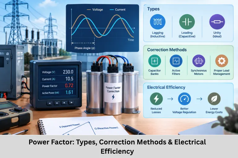
Learn power factor, power triangle, causes of low PF, correction methods, capacitor banks, harmonics, measurement, and electrical system efficiency. Embedded Tech Development Academy (ETDA).
- Power Factor: Types, Correction Methods & Electrical Efficiency
-
Power Factor: The Key to Efficient Electrical Systems
- Introduction to Power Factor
- Fundamental Concepts of Power Factor
- Types of Power Factor
- Causes of Low Power Factor
- Power Factor Correction Methods
- Active Power Factor Correction
- Harmonic Mitigation
- Power Factor Measurement and Analysis
- Economic and Capacity Considerations
- Standards and Power-Quality Requirements
- System Design Considerations
- Emerging Power-Factor Technologies
- Power Factor Troubleshooting Guide
- Frequently Asked Questions
- Conclusion
Power Factor: The Key to Efficient Electrical Systems
Introduction to Power Factor
Power factor (PF) is one of the most important parameters used to evaluate the electrical performance and efficiency of AC power systems. It describes how effectively electrical power supplied to a load is converted into useful real power. In an AC circuit, the relationship between real power, reactive power, and apparent power determines the overall power factor of the system.
For a purely resistive load, voltage and current are approximately in phase and the power factor approaches unity. However, practical electrical systems contain inductive motors, transformers, magnetic devices, power electronics, variable-frequency drives, and nonlinear loads that can introduce phase displacement and harmonic distortion. These effects increase current demand without producing an equivalent increase in useful real power.
A low power factor can increase line current, I²R losses, voltage drop, transformer loading, cable heating, and distribution-system capacity requirements. Industrial facilities may also face demand charges or power-factor-related penalties depending on their utility tariff. Therefore, power-factor correction is an important part of electrical system design, energy management, and power-quality engineering.
Understanding power factor correction, reactive power compensation, capacitor banks, harmonic distortion, apparent power, real power, reactive power, electrical efficiency, power quality, industrial power systems, and energy optimization is valuable for engineers working with electrical and embedded control systems. Embedded Tech Development Academy (ETDA) provides industry-oriented technical learning that helps engineers develop practical knowledge across electronics, embedded systems, and control technologies. For learners looking for a Top Embedded Training Institute in Bangalore, Embedded Tech Development Academy (ETDA) combines technical concepts with practical engineering exposure and assured placement support.
Fundamental Concepts of Power Factor
Power Triangle
The power triangle represents the relationship between real power, reactive power, and apparent power.
- Real Power (P): Useful power consumed by the load, measured in watts (W) or kilowatts (kW).
- Reactive Power (Q): Power exchanged between reactive components and the source, measured in VAR or kVAR.
- Apparent Power (S): Total RMS volt-ampere loading of the electrical system, measured in VA or kVA.
Key Power Factor Equations
For a sinusoidal single-phase AC system:
PF = cosθ = P/S
P = V × I × cosθ
Q = V × I × sinθ
S = V × I
and:
S² = P² + Q²
For three-phase systems, real power is commonly expressed as:
P = √3 × VL × IL × cosθ
where VL is line voltage and IL is line current.
Why Apparent Power Matters
A lower PF means that more current is required to deliver the same amount of real power. This increases loading on conductors, transformers, switchgear, and other distribution equipment.
Types of Power Factor
Displacement Power Factor
Displacement PF is associated with the phase-angle difference between the fundamental voltage and current waveforms. Inductive loads such as motors and transformers commonly produce lagging displacement power factor.
Distortion Power Factor
Distortion PF results from harmonic currents produced by nonlinear loads such as rectifiers, switching power supplies, LED drivers, and variable-frequency drives.
Total Power Factor
Total power factor considers both displacement and waveform distortion effects and therefore provides a more complete representation of AC system performance.
| Type | Characteristics | Common Causes |
|---|---|---|
| Displacement PF | Fundamental voltage-current phase difference | Motors, transformers |
| Distortion PF | Harmonic current distortion | Nonlinear electronic loads |
| Total PF | Combined displacement and distortion effects | Mixed electrical loads |
Causes of Low Power Factor
Inductive Loads
Common inductive loads include:
- Electric motors
- Transformers
- Solenoids
- Contactors
- Magnetic ballasts
- Inductive heating equipment
Motors operating significantly below rated load can have particularly poor power factor because magnetizing current remains while useful mechanical output decreases.
Nonlinear Loads
Modern electronic equipment can draw nonsinusoidal current.
Examples include:
- Variable-frequency drives
- Switched-mode power supplies
- Computers
- Battery chargers
- LED drivers
- UPS systems
- Power converters
Harmonics and Power Quality
Harmonic currents can increase RMS current, transformer losses, conductor heating, neutral loading, and electromagnetic interference. Consequently, correcting displacement PF alone may not solve a system’s total power-quality problem.
Important Design Principle
A capacitor bank can improve displacement power factor but may not correct harmonic distortion and can potentially interact with system inductance to create resonance. Harmonic analysis should therefore be performed before selecting compensation equipment in nonlinear-load environments.
Power Factor Correction Methods
Passive Power Factor Correction
Capacitor banks are commonly used to supply part of the reactive power required by inductive loads.
Capacitor Bank Configurations
- Individual compensation: Capacitor connected close to a specific motor or load.
- Group compensation: Capacitors connected at a distribution panel serving several loads.
- Central compensation: Automatic capacitor banks installed at the main distribution point.
For improving an existing load from PF₁ to PF₂:
Qc = P × (tanθ₁ − tanθ₂)
where:
Qc= required compensation in kVARP= real power in kWθ₁= original power-factor angleθ₂= target power-factor angle
Automatic Capacitor Banks
Automatic power-factor correction panels switch capacitor stages according to measured reactive demand. This is useful when industrial loads vary significantly throughout the operating cycle.
Active Power Factor Correction
Active PFC Circuits
Active PFC circuits are commonly used in electronic power supplies to shape input current closer to the voltage waveform and improve input power factor while reducing harmonic current.
Static VAR Compensation
Large electrical installations may use power-electronic compensation systems such as Static VAR Compensators (SVCs) or related technologies for dynamic reactive-power control.
Synchronous Condensers
Synchronous condensers are rotating electrical machines operated to provide or absorb reactive power and are primarily associated with large electrical networks.
Harmonic Mitigation
Passive Harmonic Filters
LC filters can be designed to attenuate selected harmonic components.
Active Harmonic Filters
Active filters use power electronics to generate compensating currents that reduce harmonic components.
Multi-Pulse Rectifiers
12-pulse, 18-pulse, and higher-pulse rectifier arrangements can reduce characteristic harmonic currents compared with conventional six-pulse rectification.
Power Factor Measurement and Analysis
Measurement Instruments
Engineers use several instruments to evaluate electrical performance:
- Digital power-factor meters
- Power-quality analyzers
- Energy meters
- Harmonic analyzers
- Clamp meters with power measurements
- Data-logging energy analyzers
Important Parameters
| Parameter | Preferred/Typical Target | Concern |
|---|---|---|
| Power Factor | Often ≥0.95 | Low PF increases current |
| Voltage THD | Common design target <5% | Excessive distortion |
| Current THD | Application dependent | High nonlinear current |
| k-Factor | Depends on transformer application | High harmonic heating |
The actual acceptable limits depend on equipment ratings, system configuration, utility requirements, and applicable standards.
Economic and Capacity Considerations
Demand and Capacity
For a given real power:
kVA = kW / PF
For example, delivering 700 kW at 0.70 PF requires approximately 1000 kVA, while delivering the same 700 kW at 0.95 PF requires approximately 737 kVA.
This reduction in apparent-power demand can release capacity in transformers, cables, switchgear, and generators.
Payback Period
A basic payback calculation is:
Payback Period = Investment Cost / Annual or Monthly Savings
For example, if a correction system costs $10,000 and produces $1,200 in monthly savings:
Payback = $10,000 / $1,200 ≈ 8.3 months
Actual savings depend on utility tariffs, operating hours, demand charges, equipment losses, and the existing electrical profile.
Standards and Power-Quality Requirements
IEEE 519
IEEE 519 provides recommendations and limits related to harmonic voltage and current distortion at points of common coupling.
IEC 61000 Series
The IEC 61000 family addresses electromagnetic compatibility and power-quality-related requirements, including harmonic emissions for applicable equipment.
EN 50160
EN 50160 specifies characteristics of supply voltage at public distribution networks within its defined scope.
Utility Requirements
Power-factor requirements and penalties vary by utility, location, customer category, and tariff structure. Therefore, engineers should verify the applicable local utility regulations rather than applying a universal PF penalty threshold.
System Design Considerations
Avoiding Overcompensation
Excessive capacitance can produce a leading power factor and undesirable voltage conditions. Automatic control should prevent unnecessary capacitor stages from remaining connected during low-load periods.
Resonance Prevention
Capacitor banks can interact with system inductance and create resonance conditions. Detuned reactors, harmonic filters, and proper system studies can reduce this risk.
Motor Compensation
Motor compensation should consider operating conditions, motor loading, switching arrangements, and the possibility of self-excitation when capacitors remain connected after motor disconnection.
Emerging Power-Factor Technologies
Smart Power-Factor Correction
Modern systems increasingly combine power-factor controllers with sensors, communication interfaces, data logging, and predictive analytics.
Wide-Bandgap Power Electronics
Silicon Carbide (SiC) and Gallium Nitride (GaN) devices enable higher switching frequencies and potentially lower losses in advanced PFC and power-conversion systems.
IoT-Based Power Monitoring
Connected power-quality meters can continuously monitor voltage, current, PF, kW, kVAR, kVA, and harmonic levels, allowing engineers to identify abnormal operating conditions.
Predictive Maintenance
Long-term electrical measurements can help identify capacitor degradation, abnormal harmonics, load changes, overheating, and other conditions before they become major failures.
Power Factor Troubleshooting Guide
| Symptom | Possible Cause | Engineering Response |
|---|---|---|
| Capacitor fuses blowing | Harmonics or overcurrent | Perform harmonic analysis and review detuning |
| PF changes significantly | Variable load | Use automatic capacitor control |
| Conductors overheating | Excessive RMS current/harmonics | Measure current and harmonic spectrum |
| Leading PF | Excessive capacitance | Disconnect unnecessary stages |
| Capacitor overheating | Harmonic current | Evaluate filter/detuned-reactor requirements |
Measurement Best Practices
- Record measurements across the complete operating cycle.
- Measure both displacement and total PF where applicable.
- Monitor voltage and current simultaneously.
- Record kW, kVAR, and kVA.
- Analyze the harmonic spectrum.
- Compare measurements under different loading conditions.
Frequently Asked Questions
What is power factor?
Power factor is the ratio of real power to apparent power in an AC system. For sinusoidal conditions, it corresponds to the cosine of the phase angle between voltage and current.
What causes low power factor?
Low PF can result from inductive loads such as motors and transformers, as well as distortion caused by nonlinear electronic equipment.
How can power factor be improved?
Common techniques include capacitor banks for reactive-power compensation, automatic PF correction panels, active PFC circuits, synchronous condensers, and power-electronic VAR compensation.
Does improving power factor reduce electricity consumption?
Power-factor correction primarily reduces reactive current and apparent-power demand. It can reduce distribution losses and demand-related charges, but it does not automatically reduce the real energy consumed by the load itself.
What is a good power factor?
A PF close to 1.0 is generally desirable, but the appropriate target depends on the electrical system, load characteristics, utility requirements, harmonic conditions, and equipment design.
Conclusion
Power factor is a fundamental parameter in AC electrical systems, power-quality engineering, energy management, industrial automation, motor control, and electrical distribution design because it directly affects current demand, equipment loading, voltage regulation, distribution losses, and available system capacity. Improving power factor through appropriate capacitor banks, automatic VAR compensation, active PFC, harmonic filters, detuned reactors, and advanced power-electronic solutions can make electrical infrastructure operate more efficiently and reliably.
However, effective power-factor correction requires more than simply installing capacitors. Engineers must analyze real power, reactive power, apparent power, displacement PF, distortion PF, harmonic spectrum, load variation, resonance conditions, transformer capacity, cable loading, and utility requirements before selecting a correction strategy. Modern smart power monitoring, Internet of Things (IoT)-enabled energy management, SiC/GaN power electronics, and predictive maintenance are further transforming how electrical systems are monitored and optimized.
For engineers interested in developing practical knowledge across embedded systems, electronics, industrial automation, control systems, and power-related technologies, Embedded Tech Development Academy (ETDA) offers industry-oriented technical training and hands-on learning. As a Top Embedded Training Institute in Bangalore, Embedded Tech Development Academy (ETDA) helps learners strengthen practical engineering skills relevant to modern industrial applications while providing assured placement support. Building strong technical fundamentals with Embedded Tech Development Academy (ETDA) can help aspiring engineers understand the interaction between embedded controllers, sensors, power electronics, and industrial electrical systems, while the institute’s assured placement support provides additional career-oriented value for learners seeking a Top Embedded Training Institute in Bangalore.
Author: ETDA Trainers
Experience: 10+ Years of Industry Experience in Embedded Systems, IoT, and Embedded C Programming