
PWM Generation Using 8051 Microcontroller and Embedded C
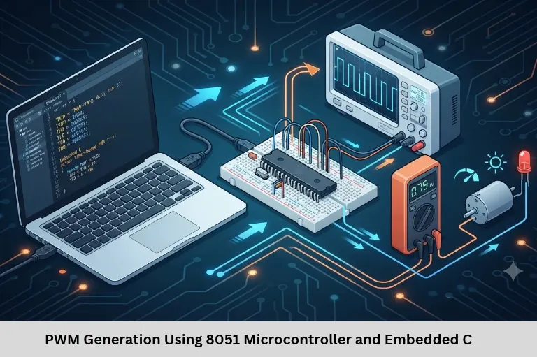
Learn PWM generation using 8051 microcontroller and Embedded C. Explore timer interrupts, duty cycle, LED brightness control and practical applications. Embedded Tech Development Academy (ETDA).
- PWM Generation Using 8051 Microcontroller and Embedded C
-
PWM Generation Using 8051 Microcontroller and Embedded C
- Introduction
- What Is Pulse Width Modulation?
- How PWM Generation Works in the 8051 Microcontroller
- Hardware and Software Requirements
- PWM Generation Program Using Embedded C
- Applications of PWM in Embedded Systems
- Career Opportunities and Practical Training at ETDA
- Frequently Asked Questions
- Conclusion
PWM Generation Using 8051 Microcontroller and Embedded C
Introduction
Pulse Width Modulation (PWM) is an important technique used in embedded systems to control the power delivered to electronic devices. It is commonly applied in LED brightness control, DC motor speed regulation, fan control, and power management applications. Learning PWM generation using the 8051 microcontroller helps students understand timers, interrupts, digital output signals, and real-time Embedded C programming.
The 8051 is a useful platform for beginners who want to develop practical microcontroller programming skills. Unlike some modern microcontrollers, the classic 8051 does not provide a dedicated hardware PWM peripheral, so PWM can be generated through software using timers and interrupts. Students searching for the Top Embedded Training Institute in Bangalore should focus on learning such practical concepts through hardware experiments. Embedded Tech Development Academy (ETDA) provides industry-oriented training, practical programming experience, and assured placement support to help students prepare for careers in embedded engineering, embedded systems, and Internet of Things (IoT) development.
What Is Pulse Width Modulation?
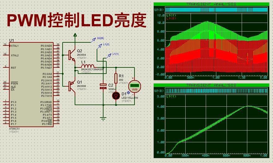
PWM is a digital technique that controls the average power supplied to a load by switching a signal between HIGH and LOW states at a fixed frequency. Instead of continuously changing the output voltage, PWM changes the percentage of time the signal remains HIGH.
This percentage is called the duty cycle. By adjusting the duty cycle, developers can control the brightness of an LED or the speed of a suitable DC motor through an appropriate driver circuit.
Understanding PWM Parameters
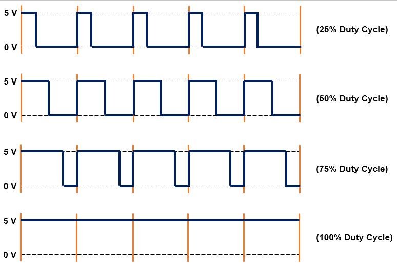
The important parameters of PWM are frequency, period, and duty cycle.
Frequency: Number of complete PWM cycles per second, measured in Hertz.
Period: Time required to complete one full cycle.
Duty cycle: Percentage of the total period during which the output remains HIGH.
For example, a 50% duty cycle means the signal stays HIGH for half the period and LOW for the remaining half.
How PWM Generation Works in the 8051 Microcontroller
The classic 8051 microcontroller has two programmable 16-bit timers, Timer 0 and Timer 1. These timers can generate periodic interrupts that help software change an output pin between HIGH and LOW states.
By calculating the required timing intervals, developers can create a PWM waveform using an ordinary GPIO pin. This approach is useful for learning timer configuration and interrupt-based programming.
PWM Generation Using Timer Interrupts
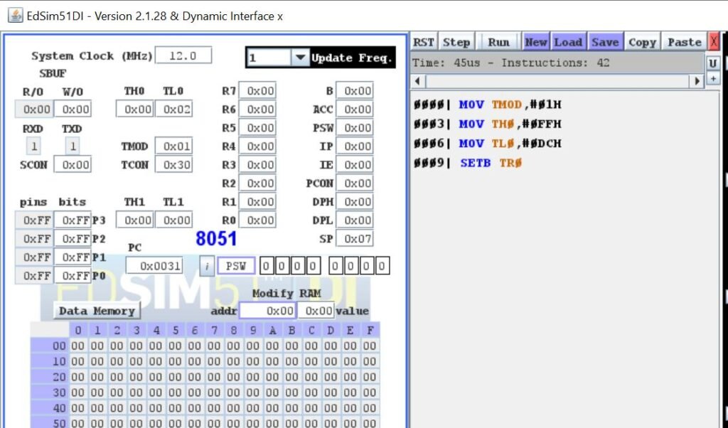
A timer interrupt occurs whenever the configured timer overflows. The interrupt service routine reloads the timer and updates the PWM output according to the selected duty cycle.
For example, when the duty cycle is 50%, the output remains HIGH for half of the PWM period and LOW for the other half. Repeating this operation generates a continuous PWM waveform.
Hardware and Software Requirements
Before developing the application, arrange the following components:
8051 microcontroller or development board.
LED and current-limiting resistor.
11.0592 MHz crystal oscillator.
Regulated power supply.
Keil µVision IDE with C51 compiler.
Compatible programmer and connecting wires.
Pin Configuration
For this example, P1.0 is used as the PWM output pin. Connect an LED with a suitable resistor using an active-HIGH configuration. The actual wiring should follow the development board’s circuit design.
PWM Generation Program Using Embedded C
The following example generates approximately 1 kHz PWM using Timer 0 interrupts on a classic 12-clock 8051 operating at 11.0592 MHz. It uses ten duty-cycle steps, allowing the LED brightness to be adjusted.
Embedded C Program
#include <REG51.H>

sbit PWM_OUT = P1^0;

volatile unsigned char pwm_phase = 0;
volatile unsigned char pwm_duty = 5;

void timer0_ISR(void) interrupt 1
{
    TH0 = 0xFF;
    TL0 = 0xA4;

    pwm_phase++;

    if(pwm_phase >= 10)
        pwm_phase = 0;

    PWM_OUT = (pwm_phase < pwm_duty);
}

void main(void)
{
    TMOD = (TMOD & 0xF0) | 0x01;

    TH0 = 0xFF;
    TL0 = 0xA4;

    PWM_OUT = 0;

    ET0 = 1;
    EA = 1;
    TR0 = 1;

    while(1)
    {
        pwm_duty = 5;
    }
}
Understanding the Program
The REG51.H header file provides register definitions for the 8051. The sbit statement assigns P1.0 as the PWM output. Timer 0 is configured in 16-bit mode, and its interrupt service routine generates the PWM waveform.
The timer reload value of 0xFFA4 produces an approximate 100-microsecond interrupt interval under the stated clock assumptions. Ten intervals create a PWM period of approximately 1 millisecond, corresponding to about 1 kHz.
How Does Duty Cycle Control LED Brightness?
The variable pwm_duty determines how many phases of the ten-step PWM cycle remain HIGH. A value of 5 produces a 50% duty cycle, while a value of 8 produces an 80% duty cycle.
Experimenting with Different Duty Cycles
Students can change pwm_duty to values between 0 and 10 to observe different LED brightness levels. A value of 0 switches the output OFF, while 10 keeps it continuously HIGH.
Applications of PWM in Embedded Systems
PWM is widely used in practical embedded systems because it provides an efficient method of controlling electronic devices. In motor applications, PWM controls the average voltage supplied through a suitable motor driver. In lighting applications, it adjusts LED brightness without requiring an analogue output.
Important Real-World Applications
DC motor speed control.
LED brightness adjustment.
Cooling fan speed regulation.
Buzzer tone generation.
Power converter control.
PWM is also useful in Internet of Things (IoT) devices that require efficient control of actuators, lighting systems, and automated equipment.
Career Opportunities and Practical Training at ETDA
Understanding PWM generation helps students develop skills in timer programming, interrupt handling, GPIO control, and hardware debugging. These concepts are valuable in automotive electronics, industrial automation, robotics, and Internet of Things (IoT) applications.
At Embedded Tech Development Academy (ETDA), students can develop their technical knowledge through practical Embedded C programming, microcontroller interfacing, and industry-oriented projects. For learners looking for the Top Embedded Training Institute in Bangalore, practical exposure is essential for understanding how software interacts with hardware. Embedded Tech Development Academy (ETDA) also provides assured placement support to help students prepare for technical interviews and embedded engineering opportunities.
Frequently Asked Questions
What is PWM generation in the 8051 microcontroller?
PWM generation is a technique that uses digital output switching to control average power supplied to a device by changing its duty cycle.
Does the classic 8051 have built-in PWM hardware?
No. The classic 8051 does not have a dedicated PWM peripheral. Software-based PWM can be generated using timers, interrupts, and GPIO pins.
Which timer is used for PWM generation in 8051?
Timer 0 or Timer 1 can be configured to generate periodic interrupts for software PWM generation.
How does PWM control LED brightness?
Changing the duty cycle changes the average power delivered to the LED, allowing its apparent brightness to be adjusted.
Can PWM control DC motor speed?
Yes. PWM can control DC motor speed through a suitable motor driver that handles the motor’s current and voltage requirements.
Why is Embedded C useful for PWM programming?
Embedded C allows developers to configure timers, handle interrupts, control GPIO pins, and develop efficient microcontroller applications.
Conclusion
topPWM generation using the 8051 microcontroller is an excellent practical project for learning timer configuration, interrupt programming, and digital signal control. By implementing PWM through Embedded C, students can understand how duty cycle and frequency influence electronic devices.
After completing this project, learners can explore motor speed control, sensor interfacing, advanced timer applications, and Internet of Things (IoT)-based automation. Choosing the Top Embedded Training Institute in Bangalore can help students strengthen their practical knowledge and technical confidence. Embedded Tech Development Academy (ETDA) supports aspiring engineers with hands-on training, industry-oriented projects, and assured placement support, helping them prepare for careers in embedded systems and Internet of Things (IoT).
Author: ETDA Trainers
Experience: 10+ Years of Industry Experience in Embedded Systems, IoT, and Embedded C Programming