
STM32 ADC Interfacing Tutorial with Practical Examples
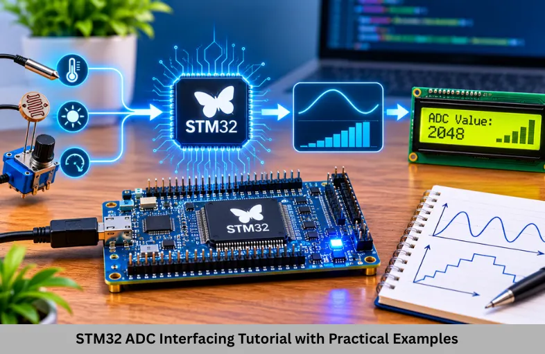
Learn STM32 ADC interfacing using STM32CubeIDE and HAL. Explore ADC resolution, voltage calculations, potentiometer interfacing, DMA, and practical examples. Embedded Tech Development Academy (ETDA).
- STM32 ADC Interfacing Tutorial with Practical Examples
-
STM32 ADC Interfacing: Analog-to-Digital Conversion with Practical Examples
- Introduction
- What Is STM32 ADC Interfacing?
- Important Features of STM32 ADC
- Understanding ADC Resolution and Voltage Calculation
- STM32 ADC Configuration Using STM32CubeIDE
- Practical Example – Potentiometer Interfacing with STM32 ADC
- Continuous ADC Conversion Mode
- STM32 ADC Interfacing Using DMA
- Applications of STM32 ADC Interfacing
- Common STM32 ADC Programming Mistakes
- Learn STM32 ADC Programming at Embedded Tech Development Academy
- Frequently Asked Questions
- Conclusion
STM32 ADC Interfacing: Analog-to-Digital Conversion with Practical Examples
Introduction
STM32 ADC interfacing is an essential topic for students learning embedded systems, microcontroller programming, and sensor interfacing. Real-world sensors such as temperature sensors, pressure sensors, light sensors, and potentiometers generate analog voltage signals. Since microcontrollers process digital data, these analog signals must be converted into digital values using an Analog-to-Digital Converter (ADC).
Understanding STM32 ADC programming helps students develop practical firmware skills for industrial automation, automotive electronics, Internet of Things (IoT) devices, and embedded product development. Students looking for structured technical learning can explore Embedded Tech Development Academy (ETDA), a Top Embedded Training Institute in Bangalore, where hands-on microcontroller training and assured placement support help learners prepare for embedded engineering careers.
What Is STM32 ADC Interfacing?
An ADC is a hardware peripheral that converts an analog voltage into a corresponding digital number. STM32 microcontrollers contain built-in ADC peripherals that allow engineers to interface with analog sensors without requiring an external ADC IC for many applications.
For example, a temperature sensor may produce 1.2V at a particular temperature. The STM32 ADC samples this voltage and converts it into a digital value that firmware can process, display, or transmit.
Important Features of STM32 ADC
STM32 ADC peripherals commonly support:
Multiple analog input channels.
Configurable ADC resolution.
Adjustable sampling time.
Single and continuous conversion modes.
Interrupt-based conversion.
DMA-based data acquisition.
ADC scan mode for multiple channels.
The exact ADC capabilities depend on the STM32 family. Some devices support 12-bit ADCs, while others offer additional resolution options and advanced conversion features.
Understanding ADC Resolution and Voltage Calculation
ADC resolution determines how many digital values are available to represent an analog input voltage.
ADC Resolution Formula
For an N-bit ADC, the number of digital levels is:
Number of levels = 2^N
For a 12-bit ADC:
2^12 = 4096 digital levels.
Therefore, the output value ranges from 0 to 4095.
ADC Digital Value Calculation
The approximate ADC output can be calculated using:
ADC Value = (Vin / Vref) × (2^N − 1)
Where:
Vin = Analog input voltage.
Vref = ADC reference voltage.
N = ADC resolution in bits.
For a 12-bit ADC with a 3.3V reference, an input voltage of 1.65V produces approximately 2048.
Converting ADC Value into Voltage
The analog voltage can be estimated using:
Vin = (ADC Value × Vref) / (2^N − 1)
This calculation is frequently used in embedded applications to convert raw ADC readings into meaningful sensor measurements.
STM32 ADC Configuration Using STM32CubeIDE
STM32CubeIDE simplifies ADC initialization through graphical peripheral configuration and automatic code generation.
Step 1 – Create an STM32 Project
Create a new project in STM32CubeIDE and select your development board or microcontroller. Open the Pinout and Configuration window to identify the analog input pin.
For example, configure PA0 as ADC input if the selected STM32 device supports ADC functionality on that pin.
Step 2 – Enable ADC Peripheral
Select the ADC peripheral and configure the required channel. Set the conversion mode, sampling time, and resolution according to your application.
Step 3 – Configure ADC Parameters
Important ADC parameters include:
Resolution: Select the supported ADC bit resolution.
Sampling Time: Determines how long the ADC samples the input.
Conversion Mode: Select single or continuous conversion.
Data Alignment: Configure right or left alignment.
Trigger Source: Select software or hardware triggering.
Step 4 – Generate Initialization Code
Generate the project code. STM32CubeIDE creates ADC initialization functions such as MX_ADC1_Init() and the required configuration structures.
Practical Example – Potentiometer Interfacing with STM32 ADC
A potentiometer is one of the easiest components for learning ADC interfacing. It produces a variable analog voltage depending on its position.
Hardware Connections
Connect the potentiometer as follows:
One terminal to 3.3V.
Another terminal to GND.
Middle terminal to the selected ADC input pin.
Ensure that the analog input voltage remains within the permitted ADC input range specified in the microcontroller datasheet.
STM32 ADC HAL Programming
The following example demonstrates ADC conversion using STM32 HAL.
#include "main.h"

uint32_t adc_value;

int main(void)
{
    HAL_Init();
    SystemClock_Config();
    MX_GPIO_Init();
    MX_ADC1_Init();

    while (1)
    {
        HAL_ADC_Start(&hadc1);

        HAL_ADC_PollForConversion(
            &hadc1, 100);

        adc_value = HAL_ADC_GetValue(&hadc1);

        HAL_ADC_Stop(&hadc1);

        HAL_Delay(100);
    }
}
The HAL_ADC_Start() function starts ADC conversion. HAL_ADC_PollForConversion() waits until conversion is complete, and HAL_ADC_GetValue() retrieves the digital result.
As the potentiometer position changes, the ADC reading also changes. This example helps students understand how analog signals become digital information inside a microcontroller.
Continuous ADC Conversion Mode
Continuous conversion mode allows the ADC to perform repeated conversions automatically.
Instead of starting every conversion individually, firmware enables continuous mode and reads successive conversion results.
Continuous Conversion Example
HAL_ADC_Start(&hadc1);

while (1)
{
    HAL_ADC_PollForConversion(
        &hadc1, 100);

    adc_value = HAL_ADC_GetValue(&hadc1);
}
Continuous conversion is useful for monitoring slowly changing sensor signals. However, applications requiring high-speed or efficient data acquisition should consider DMA instead of repeatedly polling the ADC.
STM32 ADC Interfacing Using DMA
DMA stands for Direct Memory Access. It transfers ADC conversion results directly into memory without requiring the CPU to handle every individual transfer.
ADC DMA Advantages
DMA is especially useful when:
Sampling multiple sensor channels.
Acquiring high-frequency signals.
Collecting continuous sensor data.
Reducing CPU processing overhead.
Implementing signal-processing applications.
Starting ADC Conversion with DMA
uint16_t adc_buffer[10];

HAL_ADC_Start_DMA(
    &hadc1,
    (uint32_t *)adc_buffer,
    10);
This example starts ADC conversion with DMA and stores ten conversion results in the buffer.
The ADC and DMA configuration must be completed in STM32CubeIDE before using this function. Depending on the STM32 family, DMA configuration and ADC callback behavior may differ.
Applications of STM32 ADC Interfacing
STM32 ADC programming is widely used in practical embedded engineering projects.
Sensor-Based Applications
ADC interfacing supports temperature monitoring, light intensity measurement, battery voltage monitoring, pressure measurement, and analog sensor data acquisition.
Automotive Embedded Systems
Automotive controllers use ADC peripherals to monitor analog signals such as sensor outputs, voltage levels, and certain diagnostic measurements.
IoT and Industrial Automation
ADC data can be processed locally and transmitted through communication protocols such as UART, SPI, I2C, CAN, or wireless interfaces.
These applications demonstrate why ADC programming is an important skill for students preparing for embedded firmware development roles.
Common STM32 ADC Programming Mistakes
Beginners often face ADC issues because of incorrect configuration or hardware connections.
Common mistakes include selecting the wrong ADC channel, forgetting to configure the GPIO pin in analog mode, using an incorrect sampling time, and exceeding the ADC input voltage range.
Another frequent issue is assuming that the ADC reference voltage is always exactly 3.3V. Actual reference voltage variations can affect measurement accuracy.
Students should verify ADC configuration, input connections, reference voltage, and conversion completion status while debugging their firmware.
Learn STM32 ADC Programming at Embedded Tech Development Academy
STM32 ADC interfacing provides a strong foundation for embedded C programming, sensor interfacing, and microcontroller-based application development.
At Embedded Tech Development Academy (ETDA), students can strengthen their practical understanding of embedded programming, STM32 peripherals, communication protocols, debugging, and hardware interfacing through technical learning and project-oriented practice.
Choosing a Top Embedded Training Institute in Bangalore helps students develop industry-relevant programming skills and gain exposure to practical embedded applications. Embedded Tech Development Academy (ETDA) supports learners through structured technical training and assured placement support.
Students searching for a Top Embedded Training Institute in Bangalore can explore Embedded Tech Development Academy (ETDA) to improve their understanding of ADC programming and build confidence in developing real-world embedded applications.
Frequently Asked Questions
What is STM32 ADC interfacing?
STM32 ADC interfacing allows microcontrollers to read analog voltage signals from sensors and convert them into digital values for processing.
What is the resolution of STM32 ADC?
Many STM32 microcontrollers support 12-bit ADC resolution, providing 4096 digital levels. Supported resolutions depend on the particular STM32 device.
How do I read ADC values in STM32?
Use HAL_ADC_Start(), HAL_ADC_PollForConversion(), and HAL_ADC_GetValue() to start conversion, wait for completion, and read the ADC result.
What is ADC DMA in STM32?
ADC DMA transfers conversion results automatically into memory, reducing CPU workload and supporting efficient data acquisition.
Can STM32 ADC measure temperature?
Yes. STM32 ADC can measure analog temperature sensor outputs. Some STM32 devices also include an internal temperature sensor that can be accessed through an ADC channel.
Why should students learn STM32 ADC programming?
ADC programming helps students understand sensor interfacing, analog signal measurement, embedded C, and practical microcontroller applications required for embedded engineering careers.
Conclusion
STM32 ADC interfacing is a fundamental concept for students interested in embedded systems, firmware development, Internet of Things (IoT), and automotive electronics. Understanding ADC resolution, voltage calculations, HAL programming, continuous conversion, and DMA helps students develop reliable sensor-based applications.
Practical experiments with potentiometers and analog sensors provide valuable experience in hardware interfacing and debugging. These fundamentals also prepare students for advanced topics such as signal processing, RTOS, device drivers, and embedded communication protocols.
For aspiring embedded engineers, Embedded Tech Development Academy (ETDA) offers practical technical learning opportunities to strengthen programming knowledge. Exploring a Top Embedded Training Institute in Bangalore like Embedded Tech Development Academy (ETDA) can help students develop industry-oriented skills through hands-on projects, structured training, and assured placement support.
Author: ETDA Trainers
Experience: 10+ Years of Industry Experience in Embedded Systems, IoT, and Embedded C Programming