
STM32 GPIO Programming: Input and Output Configuration Guide
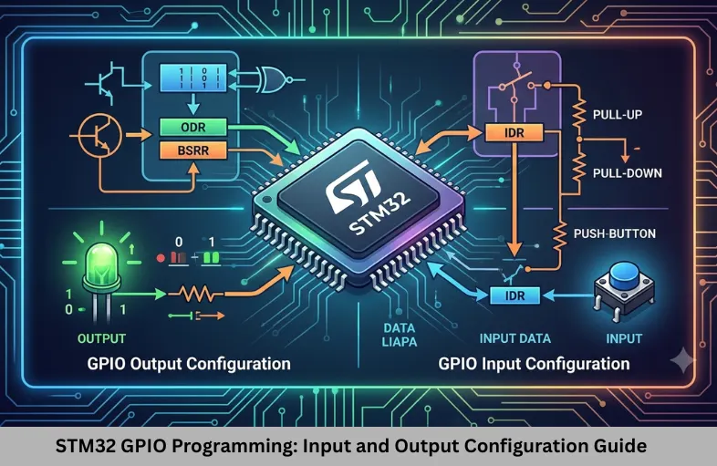
Learn STM32 GPIO programming using STM32CubeIDE and HAL. Explore GPIO input, output, pull-up, pull-down, registers, interrupts, and practical examples. Embedded Tech Development Academy (ETDA).
- STM32 GPIO Programming: Input and Output Configuration Guide
-
STM32 GPIO Programming: Complete Guide to Input and Output Configuration
- Introduction
- What Is GPIO in STM32 Microcontrollers?
- STM32 GPIO Operating Modes
- STM32 GPIO Configuration Using STM32CubeIDE
- STM32 GPIO Output Programming Using HAL
- STM32 GPIO Input Programming
- STM32 GPIO Registers and Low-Level Programming
- GPIO Interrupt Programming in STM32
- Practical STM32 GPIO Projects for Students
- Common STM32 GPIO Programming Mistakes
- Learn STM32 GPIO Programming at Embedded Tech Development Academy
- Frequently Asked Questions
- Conclusion
STM32 GPIO Programming: Complete Guide to Input and Output Configuration
Introduction
STM32 GPIO programming is one of the most important topics for students beginning their journey into embedded systems development. General-purpose input/output (GPIO) pins allow a microcontroller to communicate with external hardware such as LEDs, switches, sensors, relays, and other digital devices. Understanding GPIO configuration helps students develop practical skills in embedded C programming and hardware interfacing.
STM32 microcontrollers provide flexible GPIO configurations, including input mode, output mode, alternate function mode, and analog mode. Learning these configurations using STM32CubeIDE and STM32 HAL libraries helps beginners write structured and maintainable firmware. Students looking for practical embedded training can explore Embedded Tech Development Academy (ETDA), a Top Embedded Training Institute in Bangalore, where hands-on learning and assured placement support help learners prepare for embedded engineering opportunities.
What Is GPIO in STM32 Microcontrollers?
GPIO stands for General-Purpose Input/Output. These pins allow an STM32 microcontroller to receive digital signals from external devices or generate digital signals to control hardware.
For example, an input GPIO can detect whether a push button is pressed, while an output GPIO can switch an LED ON or OFF. GPIO programming is also fundamental to understanding peripheral interfacing, device drivers, and real-time embedded applications.
STM32 GPIO pins are organized into ports such as GPIOA, GPIOB, GPIOC, and GPIOD, depending on the specific microcontroller. Each port generally contains multiple pins identified as PA0, PA1, PB0, PB1, and so on.
STM32 GPIO Operating Modes
STM32 GPIO pins support four major operating modes. Selecting the correct mode is essential for reliable hardware interfacing.
GPIO Input Mode
Input mode allows the microcontroller to read external digital signals. A GPIO input pin can detect HIGH or LOW voltage levels depending on the connected circuit.
Common applications include push buttons, digital sensors, switches, and signal monitoring circuits. Input pins may use floating, pull-up, or pull-down configurations.
GPIO Output Mode
Output mode allows the STM32 microcontroller to generate digital signals. It is commonly used for controlling LEDs, buzzers, digital control signals, and compatible external circuits.
STM32 output pins can generally operate in push-pull or open-drain configurations. Push-pull outputs actively drive HIGH and LOW levels, while open-drain outputs require an appropriate pull-up arrangement to generate HIGH.
Alternate Function Mode
Alternate function mode allows GPIO pins to connect with internal peripherals. For example, UART, SPI, I2C, PWM, and timer signals can be routed through specific GPIO pins.
Students working on communication protocols and peripheral drivers must understand alternate function configuration because incorrect pin selection can prevent peripherals from operating correctly.
Analog Mode
Analog mode is used when GPIO pins are connected to analog peripherals such as ADC or DAC. This configuration is useful for reading analog sensor signals or generating analog output through supported peripherals.
STM32 GPIO Configuration Using STM32CubeIDE
STM32CubeIDE provides graphical configuration tools and code generation facilities that simplify GPIO initialization.
Step 1 – Create a New STM32 Project
Open STM32CubeIDE and create a project for your target STM32 development board. Select the appropriate microcontroller or board configuration.
For example, students can practice GPIO programming using STM32 Nucleo boards with compatible STM32 microcontrollers.
Step 2 – Configure GPIO Pins
Open the Pinout and Configuration section. Select a GPIO pin and configure it as GPIO_Output or GPIO_Input.
For an LED connected to PA5, configure PA5 as an output. For a push button connected to another available GPIO pin, configure that pin as an input.
Step 3 – Configure GPIO Parameters
Under GPIO settings, configure the following parameters:
Mode: Input, output push-pull, or output open-drain.
Pull-up/Pull-down: Defines the internal resistor configuration.
Output Speed: Selects the output transition speed.
User Label: Assign meaningful names such as LED_PIN or BUTTON_PIN.
Step 4 – Generate Initialization Code
Click Generate Code to create the project structure and GPIO initialization functions.
STM32CubeIDE typically generates the GPIO configuration inside the MX_GPIO_Init() function in the gpio.c file.
STM32 GPIO Output Programming Using HAL
The STM32 HAL library provides functions that simplify GPIO control without requiring direct register manipulation.
Example – LED Blinking Using STM32 GPIO
The following example demonstrates how to toggle an LED connected to GPIOA pin 5.
#include "main.h"

int main(void)
{
    HAL_Init();
    SystemClock_Config();
    MX_GPIO_Init();

    while (1)
    {
        HAL_GPIO_TogglePin(GPIOA, GPIO_PIN_5);

        HAL_Delay(500);
    }
}
The HAL_GPIO_TogglePin() function changes the current output state. HAL_Delay(500) introduces a delay of approximately 500 milliseconds.
If the LED is connected correctly and the pin is configured as an output, it will blink continuously.
Important GPIO HAL Functions
STM32 HAL provides several commonly used GPIO functions:
HAL_GPIO_WritePin(): Sets a GPIO output pin HIGH or LOW.
HAL_GPIO_ReadPin(): Reads the current input state of a GPIO pin.
HAL_GPIO_TogglePin(): Toggles the output state.
HAL_GPIO_Init(): Initializes GPIO configuration.
HAL_GPIO_DeInit(): Deinitializes GPIO configuration.
These functions are frequently used in embedded firmware development and practical microcontroller projects.
STM32 GPIO Input Programming
GPIO input programming enables the microcontroller to detect external digital signals.
Example – Reading a Push Button
Assume a push button is connected to GPIOB pin 0 and configured as an input with a pull-up resistor.
GPIO_PinState button_state;

while (1)
{
    button_state = HAL_GPIO_ReadPin(
        GPIOB, GPIO_PIN_0);

    if (button_state == GPIO_PIN_RESET)
    {
        HAL_GPIO_WritePin(
            GPIOA, GPIO_PIN_5, GPIO_PIN_SET);
    }
    else
    {
        HAL_GPIO_WritePin(
            GPIOA, GPIO_PIN_5, GPIO_PIN_RESET);
    }
}
When the button connects the input pin to ground, the pin reads LOW. The program turns the LED ON when the button is pressed and turns it OFF when released.
Understanding Pull-Up and Pull-Down Resistors
A floating GPIO input can produce unpredictable readings because the voltage level is not properly defined.
A pull-up resistor maintains a HIGH input level when the switch is open, while a pull-down resistor maintains a LOW level. STM32 microcontrollers commonly provide configurable internal pull-up and pull-down resistors.
Correct resistor configuration improves input stability and prevents unwanted switching caused by floating signals.
STM32 GPIO Registers and Low-Level Programming
Although HAL simplifies development, understanding GPIO registers is essential for embedded firmware engineers.
Important STM32 GPIO Registers
Depending on the STM32 family, GPIO configuration generally involves the following registers:
MODER: Selects input, output, alternate function, or analog mode.
OTYPER: Configures output type as push-pull or open-drain.
OSPEEDR: Configures output speed.
PUPDR: Selects pull-up, pull-down, or no-pull configuration.
IDR: Reads the input data register.
ODR: Controls the output data register.
BSRR: Sets or resets output pins efficiently.
Register names and bit layouts can vary between STM32 families, so engineers should refer to the reference manual for their target device.
Why BSRR Is Useful
The Bit Set/Reset Register provides a convenient way to modify GPIO output states without performing a read-modify-write operation on ODR.
It is particularly useful when developing efficient firmware and learning low-level microcontroller programming techniques.
GPIO Interrupt Programming in STM32
STM32 GPIO pins can also generate external interrupts through EXTI (External Interrupt/Event Controller).
Interrupt-based input handling is useful when a microcontroller needs to respond immediately to external events instead of continuously polling a pin.
For example, a push button can trigger an interrupt when its signal changes from LOW to HIGH or HIGH to LOW.
In STM32CubeIDE, configure the required GPIO pin as an external interrupt and select the appropriate trigger edge. Then implement the HAL_GPIO_EXTI_Callback() function.
void HAL_GPIO_EXTI_Callback(
    uint16_t GPIO_Pin)
{
    if (GPIO_Pin == GPIO_PIN_0)
    {
        HAL_GPIO_TogglePin(
            GPIOA, GPIO_PIN_5);
    }
}
The callback executes when the configured external interrupt occurs. Proper interrupt configuration and button debouncing are important for reliable operation.
Practical STM32 GPIO Projects for Students
Students can strengthen their embedded programming skills by implementing small GPIO-based projects.
Beginner-Level Projects
LED blinking using GPIO output.
Push-button-controlled LED.
Multiple LED sequencing.
Digital input monitoring.
Buzzer control using GPIO.
Intermediate-Level Projects
Traffic light controller.
GPIO interrupt-based button control.
Relay control with suitable driver circuitry.
Sensor status indication.
GPIO-based digital control applications.
These projects help students understand hardware connections, embedded C logic, debugging, and firmware execution.
Common STM32 GPIO Programming Mistakes
Beginners often encounter GPIO problems because of incorrect configuration or hardware connections.
Common mistakes include selecting the wrong GPIO pin, forgetting to enable the GPIO clock, using an incorrect pull-up or pull-down setting, and configuring an input pin as an output.
Another frequent problem is assuming that every GPIO pin can support every peripheral function. Alternate function mappings depend on the STM32 model and pin configuration.
Always verify the datasheet, development board schematic, and reference manual before connecting external hardware. Avoid connecting loads that exceed the GPIO pin’s electrical limits.
Learn STM32 GPIO Programming at Embedded Tech Development Academy
STM32 GPIO programming provides an excellent foundation for students interested in embedded systems, automotive electronics, Internet of Things (IoT) development, and firmware engineering.
At Embedded Tech Development Academy (ETDA), students can develop practical knowledge of embedded C, microcontroller programming, GPIO interfacing, communication protocols, peripheral configuration, and debugging.
Choosing a Top Embedded Training Institute in Bangalore helps students understand how theoretical concepts translate into practical engineering skills. Embedded Tech Development Academy (ETDA) emphasizes technical learning, hands-on exercises, and project-based exposure to embedded development.
Students searching for a Top Embedded Training Institute in Bangalore can explore Embedded Tech Development Academy (ETDA) to strengthen their programming fundamentals and build confidence in hardware interfacing. Its learning approach and assured placement support can help aspiring embedded engineers prepare for industry opportunities.
Frequently Asked Questions
What is GPIO programming in STM32?
GPIO programming allows STM32 microcontrollers to read digital inputs and control external devices through configurable input and output pins.
Which IDE is used for STM32 GPIO programming?
STM32CubeIDE is widely used for STM32 development. It supports graphical GPIO configuration, code generation, compilation, debugging, and firmware programming.
What is the difference between GPIO input and output mode?
Input mode reads external digital signals, whereas output mode generates digital signals to control compatible external devices.
What is HAL_GPIO_ReadPin() used for?
HAL_GPIO_ReadPin() reads the current logic state of a GPIO pin and returns GPIO_PIN_SET or GPIO_PIN_RESET.
Can STM32 GPIO generate interrupts?
Yes. STM32 GPIO pins can generate external interrupts using EXTI, allowing firmware to respond to selected signal transitions.
Why should students learn STM32 GPIO programming?
GPIO programming builds essential embedded C and hardware interfacing skills required for microcontroller development, peripheral programming, and embedded engineering projects.
Conclusion
STM32 GPIO programming is a fundamental skill for anyone entering embedded systems development. By understanding input and output modes, pull-up and pull-down resistors, HAL functions, GPIO registers, and external interrupts, students can develop reliable microcontroller applications.
Practicing LED control, button interfacing, and interrupt-based projects builds the foundation required for advanced topics such as UART, SPI, I2C, timers, ADC, and RTOS programming.
For students planning an embedded engineering career, Embedded Tech Development Academy (ETDA) offers practical learning opportunities to improve technical confidence. Exploring a Top Embedded Training Institute in Bangalore like Embedded Tech Development Academy (ETDA) can support your learning journey through structured training, real-time project practice, and assured placement support.
Author: ETDA Trainers
Experience: 10+ Years of Industry Experience in Embedded Systems, IoT, and Embedded C Programming