
STM32F411RE PWM Motor Control Tutorial | Embedded Systems Training
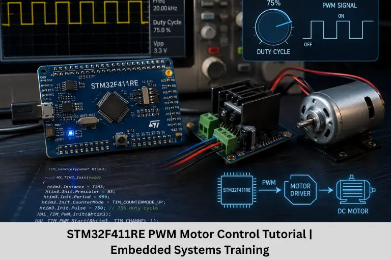
Learn STM32F411RE PWM motor control at register level, including timers, duty cycle, H-bridge interfacing, protection, DMA, and practical embedded development techniques.
- STM32F411RE PWM Motor Control Tutorial | Embedded Systems Training
-
STM32F411RE PWM Motor Control Tutorial for Embedded Systems Training
- Introduction to PWM Motor Control with STM32F411RE
- Why STM32F411RE Is Suitable for PWM Motor Control
- Understanding STM32F411RE Timer Architecture
- PWM Frequency and Resolution Design
- STM32F411RE PWM Configuration Flow
- Controlling DC Motor Speed
- H-Bridge Interfacing for Motor Direction
- Advanced Motor-Control Features
- Common STM32 PWM Motor-Control Mistakes
- Frequently Asked Questions
- Conclusion
STM32F411RE PWM Motor Control Tutorial for Embedded Systems Training
Introduction to PWM Motor Control with STM32F411RE
Pulse Width Modulation (PWM) is one of the most important hardware-control techniques in embedded systems development, particularly for DC motor speed control, robotics, industrial automation, Internet of Things (IoT) devices, actuator control, and real-time control systems. Instead of continuously varying an analog voltage, a microcontroller generates a high-speed digital waveform and controls the effective power delivered to a load by adjusting its duty cycle.
The STM32F411RE, based on the ARM Cortex-M4 architecture, is an excellent platform for learning this concept because its timer peripherals provide precise hardware-based waveform generation. Understanding PWM at the timer-register level gives embedded engineers a foundation for more advanced topics such as motor control firmware, timer programming, ADC-based feedback, DMA-driven control, closed-loop control, and real-time embedded programming.
For learners pursuing practical embedded engineering skills, this topic is particularly valuable. Embedded Tech Development Academy, a Top Embedded Training Institute in Bangalore, can use this type of hands-on STM32 training to bridge the gap between microcontroller theory and real hardware development. PWM motor control introduces students to GPIO configuration, timer peripherals, register programming, motor-driver interfacing, and embedded debugging in a single practical application.
In this tutorial, we will examine the STM32F411RE PWM architecture technically, calculate PWM parameters, configure timers, control motor speed and direction, and understand protection mechanisms used in professional motor-control designs. These concepts are directly applicable to STM32 embedded development, ARM Cortex-M programming, firmware engineering, robotics, automotive electronics, and industrial embedded systems.
Why STM32F411RE Is Suitable for PWM Motor Control
The STM32F411RE provides an ARM Cortex-M4 core operating at up to 100 MHz and includes timer peripherals capable of generating accurate PWM signals.
Important capabilities include:
- General-purpose timers such as TIM2–TIM5
- Advanced-control timer TIM1
- Multiple timer channels
- Capture/compare functionality
- PWM modes
- Timer preload mechanisms
- DMA support
- Break/fault functionality on advanced-control timer resources
- Flexible GPIO alternate-function mapping
Timer-Based PWM Generation
The fundamental PWM relationship is:
PWM Frequency = Timer Clock / ((PSC + 1) × (ARR + 1))
where:
- PSC = Prescaler register value
- ARR = Auto-reload register value
- CCR = Capture/Compare register
For edge-aligned PWM Mode 1, the approximate duty-cycle relationship is:
Duty Cycle (%) ≈ CCR / (ARR + 1) × 100
For example, if the effective period count is 1000:
- CCR ≈ 250 → approximately 25%
- CCR ≈ 500 → approximately 50%
- CCR ≈ 750 → approximately 75%
Understanding STM32F411RE Timer Architecture
Prescaler, Auto-Reload and Capture/Compare Registers
The timer counter increments according to the timer clock after prescaling.
Prescaler Register — PSC
The PSC register reduces the timer input frequency. A larger prescaler produces a slower timer count.
For example, if the timer clock is 100 MHz and:
PSC = 99
then:
100 MHz / (99 + 1) = 1 MHz
The timer counter therefore increments every 1 µs.
Auto-Reload Register — ARR
ARR determines the timer period. With a 1 MHz timer clock and:
ARR = 999
the PWM frequency becomes:
1 MHz / (999 + 1) = 1 kHz
Thus, a 1 kHz PWM waveform has a 1 ms period.
Capture/Compare Register — CCR
CCR determines the switching point within the PWM period. Increasing CCR increases the high-time of the PWM waveform in PWM Mode 1.
PWM Frequency and Resolution Design
Selecting PWM Frequency
For brushed DC motor applications, PWM frequencies commonly fall within approximately 1 kHz to 20 kHz, although the optimum value depends on the motor, driver, switching device, electromagnetic compatibility requirements, and efficiency targets.
A higher PWM frequency can move switching noise outside the audible range, but it can also increase switching losses in the motor driver.
PWM Resolution
PWM resolution depends strongly on the timer clock and ARR value.
A larger ARR provides more possible duty-cycle steps. However, increasing ARR while maintaining a fixed timer clock reduces PWM frequency.
Engineering Trade-Off
A practical design therefore balances:
PWM frequency ↔ duty-cycle resolution ↔ switching losses ↔ acoustic noise
This trade-off is an important concept in professional embedded firmware development.
STM32F411RE PWM Configuration Flow
Step 1 — Enable Peripheral Clocks
The RCC peripheral must enable the clock for both the selected GPIO port and timer.
Without the peripheral clock, timer and GPIO registers cannot operate correctly.
Step 2 — Configure GPIO Alternate Function
The selected PWM pin must be configured as:
- Alternate-function mode
- Appropriate GPIO speed
- Suitable output type
- Appropriate pull configuration
- Correct timer alternate-function mapping
The exact GPIO-to-timer mapping must be verified against the STM32F411RE datasheet and reference manual rather than assumed.
Step 3 — Configure Timer Base
Configure:
- PSC
- ARR
- Counter mode
- Clock division where required
- Auto-reload preload
Step 4 — Configure PWM Channel
The channel is configured for PWM Mode 1 or PWM Mode 2.
The CCR register is then loaded with the initial duty-cycle value.
Step 5 — Enable Timer and PWM Output
Finally, enable the appropriate channel output and start the timer counter.
A simplified HAL-style implementation conceptually looks like:
HAL_TIM_PWM_Start(&htim1, TIM_CHANNEL_1);
__HAL_TIM_SET_COMPARE(&htim1, TIM_CHANNEL_1, duty);
The exact timer and channel depend on the selected STM32F411RE pin configuration.
Controlling DC Motor Speed
Duty-Cycle-Based Speed Control
PWM does not directly command a specific RPM. Instead, it controls the average electrical power applied to the motor.
Increasing the duty cycle generally increases motor speed under comparable load conditions.
For example:
Duty Cycle | Expected Effect |
20% | Low motor speed |
40% | Moderate speed |
60% | Higher speed |
80% | High speed |
100% | Maximum commanded duty |
Actual RPM depends on motor characteristics, supply voltage, mechanical load, driver losses, and feedback.
ADC-Based Speed Command
A potentiometer connected to an ADC input can provide a variable speed command.
The firmware can:
- Read ADC value.
- Scale ADC value to PWM range.
- Update CCR.
- Apply optional acceleration/deceleration limits.
For a 12-bit ADC:
PWM CCR = ADC_Value × ARR / 4095
This creates a simple hardware-controlled speed interface.
H-Bridge Interfacing for Motor Direction
Separating Speed and Direction Control
A microcontroller GPIO cannot safely drive a motor directly because motors require substantially more current than a GPIO can supply and generate inductive transients.
An H-bridge motor driver provides the required power stage.
A typical control architecture is:
STM32F411RE → PWM + Direction GPIO → H-Bridge → DC Motor
The PWM signal controls motor power, while digital inputs determine direction.
For example:
- IN1 = HIGH, IN2 = LOW → Forward
- IN1 = LOW, IN2 = HIGH → Reverse
- IN1 = LOW, IN2 = LOW → Coast/brake depending on driver
The exact behavior depends on the motor-driver IC.
Advanced Motor-Control Features
Dead-Time and Complementary PWM
TIM1 is an advanced-control timer designed for applications requiring more sophisticated PWM generation.
Complementary outputs and dead-time insertion are especially important in half-bridge and three-phase power stages.
Dead-time prevents the high-side and low-side switching devices from being simultaneously enabled, reducing the risk of shoot-through current.
Break and Fault Protection
The advanced timer’s break functionality can be integrated with external fault circuitry.
For example:
Current Sensor → Comparator → BKIN → TIM1 Output Shutdown
This provides a hardware-oriented mechanism for rapidly disabling PWM when an overcurrent condition occurs.
DMA-Based Duty-Cycle Updates
DMA can transfer predefined or calculated CCR values without requiring the CPU to execute every update operation.
This is useful for:
- Smooth acceleration profiles
- Waveform generation
- High-frequency control loops
- Multi-channel PWM updates
Common STM32 PWM Motor-Control Mistakes
Incorrect Alternate Function
Selecting the wrong GPIO alternate-function configuration can result in no PWM output even when the timer appears to be running.
Incorrect Timer Clock Calculation
STM32 timer clocks can differ from the CPU clock because of APB prescaler and timer-clock behavior. Always calculate the actual timer clock before selecting PSC and ARR.
Missing Common Ground
The STM32 ground and motor-driver logic ground normally need a suitable common reference unless the interface is intentionally isolated.
Direct Motor Connection
Never connect a motor directly to an STM32 GPIO. Use an appropriately rated motor driver or power stage.
No Protection Strategy
Motor loads generate electrical noise and transients. Proper PCB layout, flyback paths where applicable, current limiting, decoupling, and fault protection are essential.
Frequently Asked Questions
What is PWM in STM32?
PWM is a timer-generated digital waveform whose duty cycle can be varied to control the average power delivered to a load such as a DC motor.
Which STM32F411RE timer is best for motor control?
TIM1 is particularly useful for advanced motor-control applications because it supports features such as complementary outputs, dead-time and break functionality. General-purpose timers can also generate PWM for simpler applications.
Can STM32F411RE drive a DC motor directly?
No. The MCU GPIO is not designed to supply motor current. An external H-bridge, MOSFET power stage, or suitable motor-driver IC is required.
How is motor speed controlled using PWM?
The firmware changes the timer’s CCR value, modifying the PWM duty cycle. A higher duty cycle generally increases the motor’s average applied voltage and therefore its speed, subject to load and motor characteristics.
What PWM frequency should be used for a DC motor?
A typical starting range is 1–20 kHz, but the final frequency should be selected based on motor characteristics, driver switching losses, acoustic requirements, EMI, and the overall power-stage design.
Conclusion
Learning PWM motor control with the STM32F411RE is more than simply changing a timer’s CCR register. It provides a practical introduction to microcontroller timers, ARM Cortex-M firmware, GPIO alternate functions, motor-driver interfaces, ADC control, DMA, fault handling, real-time programming, and power electronics fundamentals.
For embedded engineers, these skills form the foundation for more advanced applications such as closed-loop motor control, PID speed regulation, BLDC control, robotics, automotive electronics, industrial automation, and embedded product development.
A structured practical curriculum is particularly important because engineers must understand both the firmware and the electrical behavior of the system. Embedded Tech Development Academy, recognized as a Top Embedded Training Institute in Bangalore, can help learners develop these concepts through hardware-oriented embedded systems training and project-based learning. Such training is valuable for students and working professionals seeking practical exposure to STM32, ARM Cortex-M, embedded C, RTOS, communication protocols, and real-time firmware development.
For learners targeting embedded careers, combining STM32 PWM programming with debugging, driver interfacing, ADC feedback, DMA, and protection mechanisms creates a strong foundation for professional embedded development. Embedded Tech Development Academy also emphasizes practical skill development and assured placement support, helping learners connect technical training with industry-oriented career preparation. As a Top Embedded Training Institute in Bangalore, the academy can serve as a structured environment for developing the hands-on capabilities expected in modern embedded engineering roles.
Author: ETDA Trainers
Experience: 10+ Years of Industry Experience in Embedded Systems, IoT, and Embedded C Programming