
Timers and Counters in 8051 Microcontroller: Modes, Registers & Programming
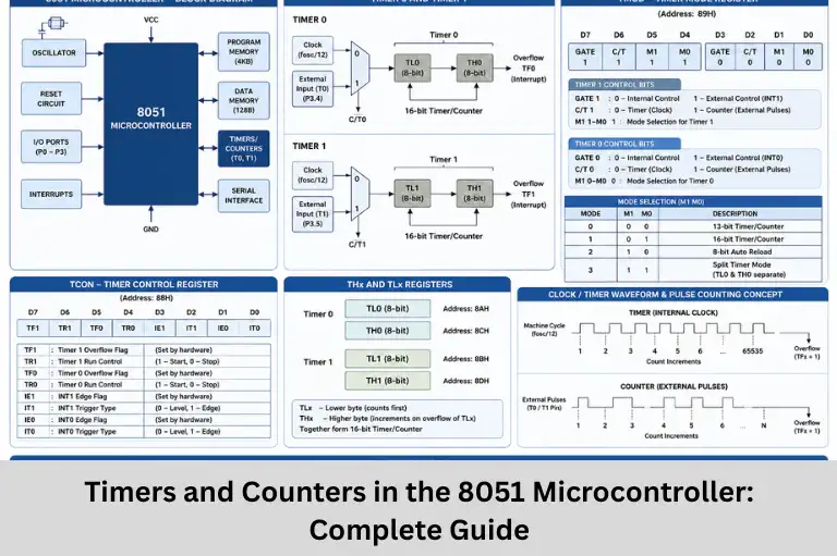
Learn Timers and Counters in the 8051 Microcontroller, including timer modes, TMOD, TCON, THx, TLx registers, delay calculations, programming examples, and applications.
- Timers and Counters in 8051 Microcontroller: Modes, Registers & Programming
-
Introduction: Understanding Timers and Counters in the 8051 Microcontroller
- What are Timers and Counters?
- Timer Mode vs Counter Mode
- Timer Registers in the 8051
- Modes of Timer Operation
- Timer Programming Example
- Delay Calculation
- Applications of Timers and Counters
- Advantages of Using Timers and Counters
- Practical Tips for Timer Programming
-
Frequently Asked Questions (FAQs)
- What is the difference between a Timer and a Counter in the 8051 microcontroller?
- How many timers are available in the 8051 microcontroller?
- What is the function of the TMOD register?
- Why is Timer Mode 2 commonly used for serial communication?
- What are the practical applications of timers and counters in embedded systems?
- Conclusion
Introduction: Understanding Timers and Counters in the 8051 Microcontroller
Timers and Counters are among the most powerful built-in peripherals of the 8051 microcontroller, enabling precise timing and event-counting operations in embedded systems. Whether you’re generating accurate delays, measuring time intervals, counting external pulses, controlling motor speed, or configuring serial communication, timers and counters play a critical role in designing reliable embedded applications.
The 8051 microcontroller includes two integrated 16-bit Timers/Counters (Timer 0 and Timer 1) that can operate either as timers, using the internal clock source, or as counters, using external input signals. These versatile peripherals eliminate the need for additional timing hardware, making embedded systems more efficient, compact, and cost-effective.
Modern embedded applications such as industrial automation, Internet of Things (IoT) devices, robotics, digital clocks, frequency measurement systems, motor control, pulse generation, traffic control systems, sensor interfacing, and UART communication rely heavily on accurate timing mechanisms. Understanding how to configure timer registers such as TMOD, TCON, TH0, TL0, TH1, and TL1, along with timer operating modes, is essential for developing real-time embedded software.
Important concepts such as 8051 timer programming, counter mode, timer mode, delay generation, baud rate generation, interrupt handling, machine cycle calculation, pulse counting, event counting, PWM generation, serial communication, embedded C programming, and microcontroller peripherals form the foundation of embedded systems programming.
For students and aspiring embedded engineers, gaining hands-on experience with timer and counter programming is crucial. Embedded Tech Development Academy (ETDA) offers industry-focused embedded systems training that combines theoretical concepts with practical laboratory sessions, real-time projects, and microcontroller programming. Through hands-on learning, students develop the skills needed for careers in embedded systems, Internet of Things (IoT), robotics, electronics design, and industrial automation.
In this article, you’ll learn the fundamentals of Timers and Counters in the 8051 Microcontroller, their working principles, timer registers, operating modes, programming examples, delay calculations, real-world applications, and practical implementation techniques.
What are Timers and Counters?
The 8051 microcontroller contains two built-in 16-bit Timer/Counter modules:
- Timer 0
- Timer 1
These modules can perform timing operations using the internal clock or count external events received through dedicated input pins.
Main Functions of Timers and Counters
- Time delay generation
- Event counting
- Frequency measurement
- PWM generation
- UART baud rate generation
- Real-time timing operations
Timer Mode vs Counter Mode
The same hardware can operate in either Timer Mode or Counter Mode.
| Feature | Timer Mode | Counter Mode |
|---|---|---|
| Clock Source | Internal Crystal Oscillator | External Signal (T0/T1 Pins) |
| Increment | Machine Cycle Based | External Pulse Based |
| Primary Use | Delay Generation | Pulse/Event Counting |
Timer Mode
In Timer Mode, the timer increments automatically according to the internal machine cycle.
Typical applications include:
- Time delays
- Digital clocks
- PWM generation
- Serial communication
Counter Mode
Counter Mode increments the register whenever an external pulse is detected.
Applications include:
- Object counting
- Frequency counters
- Pulse measurement
- Sensor event counting
Timer Registers in the 8051
The 8051 uses several Special Function Registers (SFRs) for timer control.
1. Timer Control Register (TCON)
The TCON register controls timer operation and stores overflow flags.
Important Bits
| Bit | Name | Function |
|---|---|---|
| TF1 | Timer 1 Overflow Flag | Set when Timer 1 overflows |
| TR1 | Timer 1 Run Control | 1 = Start, 0 = Stop |
| TF0 | Timer 0 Overflow Flag | Set when Timer 0 overflows |
| TR0 | Timer 0 Run Control | 1 = Start, 0 = Stop |
Purpose of TCON
The TCON register starts, stops, and monitors timer overflow events.
Important Fields
| Bits | Timer | Function |
|---|---|---|
| M1, M0 | Timer 0/1 | Select Timer Mode |
| C/T | Timer 0/1 | 0 = Timer, 1 = Counter |
| GATE | Timer 0/1 | Controls External Gating |
3. Timer Registers (THx and TLx)
Timer values are stored in:
- TH0
- TL0
- TH1
- TL1
These registers hold the current timer count.
Modes of Timer Operation
The 8051 supports several timer operating modes.
Mode 0 (13-bit Timer)
Features include:
- 13-bit timer operation
- Legacy compatibility
- Rarely used in modern applications
Mode 1 (16-bit Timer)
Mode 1 is the most commonly used timer mode.
Features
- Full 16-bit timer
- Maximum count = 65,535
- Overflow at 65,536
- Suitable for long delays
Applications include:
- Delay generation
- Digital clocks
- Embedded timing systems
Mode 2 (8-bit Auto Reload)
Mode 2 automatically reloads the timer after overflow.
Features
- 8-bit timer
- Automatic reload
- Constant time intervals
Applications include:
- UART baud rate generation
- Periodic interrupts
- Pulse generation
Mode 3 (Split Timer Mode)
Only Timer 0 supports Mode 3.
Features
- Splits Timer 0 into two 8-bit timers
- Allows simultaneous timing operations
- Increases flexibility
Choosing the Right Timer Mode
The selection depends on the application:
- Long delays → Mode 1
- Repetitive timing → Mode 2
- Multiple timers → Mode 3
Timer Programming Example
Timer 0 in Mode 1
The following Assembly program generates a delay using Timer 0.
ORG 0000H
MOV TMOD,#01H

HERE:
MOV TL0,#0F2H
MOV TH0,#0FFH

SETB TR0

WAIT:
JNB TF0,WAIT

CLR TR0
CLR TF0

SJMP HERE

END
Program Explanation
- Configure Timer 0 in Mode 1
- Load initial timer value
- Start Timer
- Wait for overflow
- Stop Timer
- Clear overflow flag
- Repeat continuously
Delay Calculation
For an 11.0592 MHz crystal oscillator:
Machine Cycle
= 12 / 11.0592 MHz
≈ 1.085 μs
Delay Formula
Delay = (FFFFH − Initial Value) × Machine Cycle
This formula helps determine precise software delays.
Applications of Timers and Counters
Timers and counters are widely used in embedded systems.
Common Applications
- Digital clocks
- Real-Time Clock (RTC)
- PWM generation
- Motor speed control
- UART baud rate generation
- Traffic light controllers
- Industrial automation
- Frequency counters
- Pulse counting systems
- Robotics
- IoT devices
- Sensor interfacing
Advantages of Using Timers and Counters
Benefits
- Accurate timing
- High-speed operation
- Hardware-based timing
- Reduced CPU workload
- Easy programming
- Supports interrupt-driven applications
Practical Tips for Timer Programming
Best Practices
- Select the appropriate timer mode.
- Calculate timer preload values carefully.
- Always clear overflow flags.
- Use interrupts for efficient timing.
- Verify machine cycle calculations.
- Test timer accuracy using an oscilloscope whenever possible.
Programming Tip
Using hardware timers instead of software delay loops improves system accuracy and processor efficiency.
Frequently Asked Questions (FAQs)
What is the difference between a Timer and a Counter in the 8051 microcontroller?
A Timer uses the internal clock to generate time delays, while a Counter uses external pulses received on the T0 or T1 pins to count events.
How many timers are available in the 8051 microcontroller?
The standard 8051 microcontroller has two built-in 16-bit timers: Timer 0 and Timer 1, which can operate as either timers or counters.
What is the function of the TMOD register?
The TMOD (Timer Mode) register configures the operating mode of Timer 0 and Timer 1, including timer/counter selection, mode selection, and gate control.
Why is Timer Mode 2 commonly used for serial communication?
Mode 2 is an 8-bit auto-reload mode that automatically reloads the timer value after overflow, making it ideal for generating accurate UART baud rates.
What are the practical applications of timers and counters in embedded systems?
Timers and counters are used for delay generation, PWM control, frequency measurement, digital clocks, UART communication, event counting, motor control, robotics, IoT devices, and industrial automation.
Conclusion
Timers and Counters are among the most valuable peripherals available in the 8051 microcontroller, enabling accurate time delay generation, event counting, pulse measurement, UART baud rate generation, PWM generation, interrupt handling, and real-time embedded control. By understanding TMOD, TCON, THx, TLx registers, timer modes, machine cycle calculations, timer interrupts, and counter operations, developers can design reliable and efficient embedded applications.
These peripherals are extensively used in industrial automation, robotics, Internet of Things (IoT) devices, consumer electronics, motor control systems, medical equipment, automotive electronics, communication systems, and embedded control applications. A strong understanding of 8051 timer programming, embedded C, assembly language, real-time programming, and microcontroller peripherals provides an excellent foundation for advanced embedded systems development.
At Embedded Tech Development Academy (ETDA), students gain practical exposure to timer programming through hands-on embedded labs, real-time projects, microcontroller interfacing, Internet of Things (IoT) applications, PCB design, and embedded C programming. ETDA‘s industry-oriented training helps learners bridge the gap between academic concepts and real-world embedded product development, preparing them for rewarding careers in embedded systems, electronics, semiconductor industries, and automation.
Whether you’re an engineering student, electronics enthusiast, or embedded systems developer, mastering Timers and Counters in the 8051 Microcontroller is a fundamental step toward building high-performance and reliable embedded applications.
Author: ETDA Trainers
Experience: 10+ Years of Industry Experience in Embedded Systems, IoT, and Embedded C Programming