
USB Interfacing with LPC1768 ARM Cortex-M3
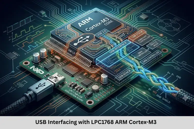
Learn USB interfacing with the LPC1768 microcontroller, including hardware connections, USB descriptors, endpoints, firmware configuration, and applications. Embedded Tech Development Academy (ETDA).
- USB Interfacing with LPC1768 ARM Cortex-M3
-
Interfacing USB with ARM Cortex-M3 Processor-Based LPC1768 Controller
- Introduction to USB Interfacing with LPC1768
- 1. Overview of USB Support in LPC1768
- 2. Hardware Requirements and USB Pin Connections
- 3. USB Operating Modes
- 4. Firmware Steps for USB Interfacing
- 5. Testing and Troubleshooting USB Communication
- 6. Applications of USB on LPC1768
- Frequently Asked Questions
- Conclusion
Interfacing USB with ARM Cortex-M3 Processor-Based LPC1768 Controller
Introduction to USB Interfacing with LPC1768
Universal Serial Bus (USB) is one of the most widely used communication interfaces in embedded systems because it supports standardized data transfer, device configuration, and convenient connectivity with computers and peripherals. The NXP LPC1768 microcontroller, based on the ARM Cortex-M3 processor, provides integrated USB controller functionality that makes it suitable for applications such as data loggers, firmware update tools, USB serial interfaces, Human Interface Devices (HID), and measurement instruments.
The LPC1768 supports USB 2.0 Full-Speed communication at up to 12 Mbps and provides hardware resources for implementing USB device and host applications. Its USB subsystem includes endpoint management and dedicated USB memory, reducing the need for an external USB controller. Successful implementation still requires correct clock configuration, pin multiplexing, electrical connections, USB descriptors, endpoint handling, and protocol-compliant firmware.
For embedded developers, understanding USB device enumeration, control transfers, USB classes, and firmware debugging is essential for developing reliable communication interfaces. These skills also connect with Embedded C programming, ARM Cortex-M3 architecture, peripheral configuration, and hardware-software integration. Embedded Tech Development Academy (ETDA) supports practical embedded technology learning, while students researching the Top Embedded Training Institute in Bangalore can prioritize hands-on microcontroller projects and USB firmware development. With assured placement support, Embedded Tech Development Academy (ETDA) aims to help learners prepare for embedded software and firmware development roles.
1. Overview of USB Support in LPC1768
The LPC1768 integrates a USB 2.0 Full-Speed controller operating at a signaling rate of 12 Mbps. Its USB subsystem supports device functionality and host functionality, with OTG-related capabilities depending on the controller configuration and board implementation.
Main USB Features
- USB device and host controller functionality.
- Integrated USB transceiver.
- Dedicated USB memory for endpoint data and controller operation.
- Control, bulk, interrupt, and isochronous transfer support where applicable.
- Endpoint and USB interrupt management.
- Support for implementing standard USB classes through suitable firmware stacks.
Common USB Device Classes
- HID: Keyboards, mice, and custom human-interface devices.
- CDC: Virtual COM ports and serial-style communication.
- MSC: USB mass-storage devices.
- Custom USB: Application-specific interfaces using suitable endpoints and protocol handling.
2. Hardware Requirements and USB Pin Connections
Essential Components
A typical LPC1768 USB project requires an LPC1768 development board, a suitable USB connector, a shielded cable, ESD protection, correct power supplies, and any board-specific signal-conditioning components.
Important USB Signals
| USB signal | LPC1768 pin | Function |
|---|---|---|
| USB D+ (DP) | P0.29 | Positive USB data line |
| USB D− (DM) | P0.30 | Negative USB data line |
| USB VBUS | P1.30 | VBUS sensing input |
| USB_CONNECT | P2.9 | Device connection control, as configured by the board |
| USB_UP_LED | P1.18 | USB status indication, if used by the design |
Verify these assignments against the LPC1768 datasheet, board schematic, and selected USB operating mode before connecting hardware.
PCB Layout and Signal Integrity
USB D+ and D− should be routed as a controlled-impedance differential pair, typically targeting 90 Ω differential impedance. Keep the traces short, closely coupled, and appropriately matched in length. Add ESD protection near the connector and follow the controller and board reference design for series resistors and pull-up control.
Power and Clock Requirements
USB requires an accurate 48 MHz clock for Full-Speed operation. Configure the clock system according to the LPC1768 reference manual and the selected board’s oscillator arrangement. VBUS sensing, USB power switching, and connector wiring must follow the requirements of the chosen host or device configuration.
3. USB Operating Modes
USB Device Mode
In device mode, the LPC1768 connects to a USB host such as a PC. Common applications include a CDC virtual COM port, HID interface, custom data-transfer device, and firmware update interface.
USB Host Mode
In host mode, the controller manages supported external USB peripherals, such as keyboards or flash drives. Host operation requires correct VBUS power management, device enumeration, and support for the attached peripheral’s class.
USB OTG
USB On-The-Go allows supported systems to switch between host and device roles. Actual role switching depends on controller support, connector wiring, board circuitry, and firmware configuration. For many beginner projects, device mode is the simplest starting point.
4. Firmware Steps for USB Interfacing
Step 1: Configure USB Pins
Set the pin multiplexing registers so P0.29 and P0.30 are assigned to USB D+ and D−. Configure the VBUS sensing and connection-control signals according to the selected mode and hardware design.
The exact PINSEL register values depend on the LPC1768 pin-function tables. Confirm each value against the device documentation rather than copying register settings without verification.
Step 2: Enable USB Power and Clocks
Enable the required peripheral power and USB clock controls. Confirm that the controller receives the correct clock and that USB-related memory and interrupt resources are initialized. Register names and initialization order should follow the selected LPCOpen, Keil, or other supported library.
Step 3: Configure the 48 MHz USB Clock
Configure the appropriate PLL and clock-divider settings to generate the required USB clock. Wait for the PLL to lock and follow the documented connection and feed sequence. Incorrect clock settings can prevent reliable enumeration or cause communication failures.
Step 4: Initialize the USB Controller
Reset and initialize the controller, configure endpoint resources, clear pending interrupt flags, and enable the required USB interrupts. When using a USB stack, let its initialization routines manage controller-specific register operations wherever possible.
Step 5: Define USB Descriptors
USB descriptors tell the host how to identify and configure the device.
- Device descriptor: Specifies USB version, vendor ID (VID), product ID (PID), and device-level information.
- Configuration descriptor: Describes the configuration and its power characteristics.
- Interface descriptor: Identifies a functional interface and its class.
- Endpoint descriptor: Defines endpoint address, transfer type, packet size, and interval where applicable.
- String descriptors: Provide optional human-readable manufacturer, product, and serial-number information.
Incorrect descriptors can cause enumeration failures or prevent the host from loading the expected driver. VID/PID values must be assigned legitimately.
Step 6: Configure Endpoints and Transfers
Endpoint zero (EP0) is mandatory and handles control transfers, including standard enumeration requests. Other endpoints support application data.
| Transfer type | Typical application |
|---|---|
| Control | Enumeration and device configuration |
| Bulk | CDC data and mass-storage transfers |
| Interrupt | HID reports and periodic event data |
| Isochronous | Time-sensitive audio or streaming data |
Endpoint allocation and buffer configuration must match the descriptors and the controller’s USB memory requirements.
Step 7: Handle USB Events
The firmware must respond to setup packets and standard requests, including requests for descriptors, device address assignment, and configuration selection. Interrupt handlers or the USB stack process these events and manage endpoint state.
Step 8: Implement the USB Class
A CDC device needs appropriate bulk data handling and class-specific requests, including line-coding support when required. HID firmware must format reports according to its report descriptor. Mass-storage implementations require bulk transport handling and appropriate SCSI command support.
Using a maintained USB stack can reduce implementation effort and protocol errors. Options include suitable NXP libraries, Keil USB middleware, and TinyUSB where the target and controller are supported.
5. Testing and Troubleshooting USB Communication
Common Problems
- Device not detected: Check the cable, connector wiring, VBUS sensing, clock configuration, and connection-control signal.
- Enumeration failure: Validate descriptors, EP0 handling, and USB reset processing.
- Data corruption: Inspect endpoint configuration, buffer management, and firmware synchronization.
- Intermittent disconnection: Check power stability, ESD protection, signal integrity, and clock accuracy.
Use the host operating system’s USB diagnostic tools, serial logs where available, and a USB protocol analyzer for deeper troubleshooting. Test connection, reset, suspend/resume, repeated transfers, and recovery from communication errors.
6. Applications of USB on LPC1768
USB interfacing can support data logging, PC-based configuration utilities, USB-to-serial interfaces, HID controllers, firmware update tools, test instruments, and supported mass-storage applications. The correct application depends on available memory, endpoint resources, the selected USB class, and firmware complexity.
At Embedded Tech Development Academy (ETDA), practical exercises involving Embedded C, ARM microcontrollers, peripheral interfaces, and firmware debugging can help learners understand these implementations. Students comparing the Top Embedded Training Institute in Bangalore should look for real hardware projects and protocol-level debugging practice. Embedded Tech Development Academy (ETDA) also provides assured placement support to help learners work toward embedded technology opportunities.
Frequently Asked Questions
What USB speed does the LPC1768 support?
The LPC1768 supports USB 2.0 Full-Speed signaling at up to 12 Mbps.
Which pins are used for USB on the LPC1768?
P0.29 and P0.30 are used for USB D+ and D−, respectively. Other signals, including VBUS sensing and connection control, must be verified against the datasheet and board schematic.
What are USB descriptors?
USB descriptors are structured data that identify the device and describe its configurations, interfaces, endpoints, and optional strings. The host uses them during enumeration.
Which USB stack can be used with LPC1768?
A suitable NXP USB library or Keil USB middleware may be used. TinyUSB is another option if the chosen version and controller implementation support the target hardware.
Why does an LPC1768 USB device fail to enumerate?
Common causes include incorrect clock configuration, invalid descriptors, incorrect pin multiplexing, VBUS sensing issues, connection-control errors, and faulty EP0 request handling. Verify these systematically using the board documentation and USB diagnostic tools.
Conclusion
Interfacing USB with the LPC1768 ARM Cortex-M3 microcontroller involves more than connecting a cable. Developers must configure the USB pins and clock, establish correct electrical connections, initialize controller resources, create valid descriptors, configure endpoints, and implement standard USB requests and class-specific behavior. Reliable USB communication also depends on signal integrity, power management, correct buffer handling, and systematic testing.
A structured understanding of USB 2.0 Full-Speed, CDC, HID, endpoint transfers, device enumeration, and firmware debugging provides a strong foundation for developing connected embedded products. Embedded Tech Development Academy (ETDA) helps learners build practical embedded systems knowledge through technical learning. Those evaluating the Top Embedded Training Institute in Bangalore can prioritize hands-on LPC1768 development and USB implementation projects. With assured placement support, Embedded Tech Development Academy (ETDA) aims to help aspiring engineers prepare for firmware development, microcontroller programming, and embedded communication roles.
Author: ETDA Trainers
Experience: 10+ Years of Industry Experience in Embedded Systems, IoT, and Embedded C Programming