
What Is UART Communication? Working, Protocol & Applications | ETDA
Learn UART communication, including its working principle, frame format, baud rate, registers, interrupts, UART vs USART, applications, and embedded examples. Embedded Tech Development Academy (ETDA).
- What Is UART Communication? Working, Protocol & Applications | ETDA
-
What Is UART Communication? Working, Protocol & Applications
- What Is UART Communication?
- How UART Communication Works
- UART Frame Format
- Stop Bits in UART
- What Is Baud Rate?
- UART Transmitter and Receiver
- UART Registers in Microcontrollers
- UART Polling vs Interrupt-Based Communication
- UART FIFO and Buffering
- UART Error Conditions
- UART Hardware Flow Control
- UART Applications
- UART vs SPI vs I2C
- UART in Embedded C
- How to Learn UART Communication
- Learn UART and Embedded Systems at ETDA
-
Assured Placement Support at ETDA
- Placement Preparation
- FAQs
- What is UART communication?
- What does UART stand for?
- What is baud rate in UART?
- What is 9600 8N1 UART?
- What are TX and RX in UART?
- Is UART synchronous or asynchronous?
- What is the difference between UART and SPI?
- What is a UART interrupt?
- Where is UART used?
- Does ETDA provide placement support?
- Conclusion
What Is UART Communication? Working, Protocol & Applications
UART, or Universal Asynchronous Receiver/Transmitter, is one of the most widely used serial communication interfaces in embedded systems. It allows two devices to exchange data serially using a relatively simple hardware interface.
UART is commonly found in microcontrollers, development boards, GPS modules, Bluetooth modules, GSM modems, debugging interfaces, industrial equipment, and many other electronic systems.
For engineering students learning embedded systems, understanding UART is essential because it introduces important concepts such as serial data transmission, baud rate, start and stop bits, parity, interrupts, buffers, and hardware registers. Students looking for a Top Embedded Training Institute in Bangalore can develop practical UART and embedded communication skills through Embedded Tech Development Academy (ETDA), along with hands-on projects and assured placement support.
What Is UART Communication?
UART stands for Universal Asynchronous Receiver/Transmitter.
It is a hardware communication peripheral that converts parallel data from a processor into serial data for transmission and converts received serial data back into parallel data.
Unlike synchronous protocols such as SPI and I2C, UART does not normally transmit a separate clock signal between the communicating devices.
Instead, both devices agree on communication parameters such as:
- Baud rate
- Number of data bits
- Parity
- Number of stop bits
UART Communication Flow
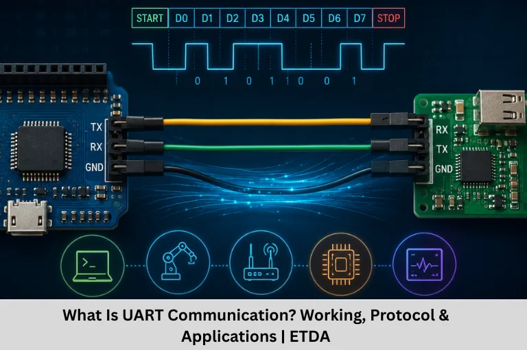
A simplified UART communication path is:
Microcontroller → UART Transmitter → TX Line → RX Line → UART Receiver → Microcontroller
For bidirectional communication:
Device A TX → Device B RX
Device A RX ← Device B TX
Important UART Signals
A basic UART connection commonly uses:
- TX — Transmit
- RX — Receive
- GND — Ground
Why Ground Is Important
Both devices need a common electrical reference for reliable communication in a typical single-ended UART connection.
How UART Communication Works
UART sends data one bit at a time.
Suppose a microcontroller wants to transmit a byte. The UART peripheral adds framing information around the data and sends the resulting serial bit stream through the TX pin.
UART Transmission Sequence
A typical UART frame consists of:
Start Bit → Data Bits → Optional Parity Bit → Stop Bit
The receiver detects the start bit, samples the incoming bits according to the configured timing, checks the frame, and reconstructs the original data byte.
Idle State
In a common UART configuration, the TX line remains at the logic HIGH state when no data is being transmitted.
Start Bit
Transmission begins with a start bit, typically represented by a LOW level.
The transition from the idle state alerts the receiver that a frame is beginning.
UART Frame Format
A UART frame defines how individual bits are organized during transmission.
Start Bit
The start bit indicates the beginning of a frame.
In a common configuration, one start bit is used.
Data Bits
UART commonly supports configurations such as:
- 5 data bits
- 6 data bits
- 7 data bits
- 8 data bits
- In some UART implementations, 9 data bits
An 8-bit data configuration is particularly common.
Least Significant Bit First
Many UART configurations transmit the least significant bit first.
For example, if a byte contains a particular binary value, the bit order on the serial line follows the UART configuration rather than simply transmitting the printed binary representation from left to right.
Parity Bit
Parity is optional and can provide a basic form of error detection.
Common configurations include:
- No parity
- Even parity
- Odd parity
Stop Bits in UART
Stop bits indicate the end of a UART frame.
Common Stop Bit Configurations
UART peripherals commonly support:
- 1 stop bit
- 1.5 stop bits
- 2 stop bits
The exact options depend on the UART hardware.
Why Stop Bits Are Needed
The stop period provides the receiver with a defined frame-ending condition and timing margin before another frame begins.
Example UART Configuration
A common configuration is:
9600 baud, 8 data bits, no parity, 1 stop bit
This is often written as:
9600 8N1
What Is Baud Rate?
Baud rate describes the number of signal symbols transmitted per second.
In a typical simple UART configuration where one bit corresponds to one symbol, the baud rate numerically corresponds to the bit rate.
Common UART Baud Rates
Examples include:
- 1200
- 2400
- 4800
- 9600
- 19200
- 38400
- 57600
- 115200
Why Baud Rate Must Match
The transmitter and receiver need compatible communication timing.
For example, if one device transmits at 115200 baud while the other expects 9600 baud, the receiver will generally interpret the incoming signal incorrectly.
Baud Rate Error
Actual UART timing is derived from the peripheral clock and divider configuration. Therefore, clock accuracy and baud-rate generation affect communication reliability.
UART Transmitter and Receiver
UART hardware generally contains separate transmit and receive logic.
UART Transmitter
The transmitter:
- Receives data from the CPU or software.
- Places the data into a transmit register or buffer.
- Adds frame information.
- Converts the data into a serial stream.
- Sends the bits through TX.
Transmit Buffer
Many microcontrollers provide transmit registers or FIFOs so the CPU does not have to manage every individual bit.
Transmit Status
UART status registers can indicate conditions such as:
- Transmit buffer empty
- Transmission complete
- Transmit FIFO status
UART Receiver
The receiver monitors the RX pin.
When it detects a valid start condition, it samples the incoming data according to the configured baud rate and reconstructs the received byte.
Receive Buffer
The received data is stored in a receive register or FIFO.
Receive Status
Status flags may indicate:
- Data available
- Overrun
- Parity error
- Framing error
- Noise error
UART Registers in Microcontrollers
UART peripherals are controlled through hardware registers.
Common UART Register Categories
Depending on the microcontroller, registers may control:
- Transmit data
- Receive data
- Baud-rate configuration
- Control settings
- Status flags
- Interrupts
- FIFO configuration
Control Registers
Control registers can configure parameters such as:
- Data length
- Parity
- Stop bits
- Enable/disable transmitter
- Enable/disable receiver
- Interrupt settings
Status Registers
Status registers provide information about the current UART state.
For example, firmware may check whether a receive-data flag is set before reading received data.
UART Polling vs Interrupt-Based Communication
There are two common ways to handle UART communication in firmware.
Polling
In polling, the CPU repeatedly checks a UART status flag.
Conceptually:
Advantages of Polling
- Simple to implement
- Easy for beginners
- Useful for basic applications
Disadvantages
The CPU may waste processing time while waiting for incoming data.
Interrupt-Based UART
With interrupt-based communication, the UART peripheral generates an interrupt when a relevant event occurs.
For example:
Data Received → UART Interrupt → ISR → Read Data
Advantages
Interrupts allow the CPU to perform other tasks while waiting for communication events.
Practical Applications
Interrupt-driven UART is useful for:
- Continuous serial communication
- Command interfaces
- GPS data
- Modem communication
- Debugging
- Embedded protocols
UART FIFO and Buffering
A FIFO, or First-In First-Out buffer, can temporarily store multiple received or transmitted bytes.
Why FIFO Is Useful
Without buffering, the CPU may need to respond immediately to every incoming byte.
A FIFO provides additional time for the processor to handle the data.
Software Buffers
Firmware can also implement circular buffers.
A typical receive architecture is:
UART RX → ISR → Circular Buffer → Application
Circular Buffer
A circular buffer uses read and write indexes that wrap around when they reach the end of the allocated memory.
This is particularly useful for continuous UART data streams.
UART Error Conditions
UART hardware can detect several types of communication errors.
Framing Error
A framing error can occur when the expected stop-bit condition is not detected at the appropriate time.
Parity Error
If parity checking is enabled and the received parity does not match the expected value, the UART can report a parity error.
Overrun Error
An overrun can occur when new received data arrives before previously received data has been processed or removed from the receive buffer.
Noise Error
Some UART peripherals can detect abnormal signal sampling or noise conditions and report them through status flags.
UART Hardware Flow Control
Basic UART communication may use only TX and RX. However, some systems require hardware flow control.
RTS and CTS
Two commonly used hardware flow-control signals are:
- RTS — Request To Send
- CTS — Clear To Send
These signals can help control data flow between devices.
Why Flow Control Is Needed
If a receiver cannot process data quickly enough, flow control can prevent excessive incoming data from overwhelming its buffers.
Hardware vs Software Flow Control
Hardware flow control uses physical signals, while software flow control uses special control characters or protocol mechanisms.
UART Applications
UART is used in many embedded applications because of its simplicity and availability.
Debugging and Console Access
Engineers frequently use UART to print:
- Debug messages
- Sensor values
- Error information
- System status
- Boot messages
A USB-to-UART adapter can allow a computer to communicate with an embedded development board.
GPS Modules
GPS receivers often provide location and timing information through serial communication.
GSM and Cellular Modules
Cellular modules can be controlled using serial commands, often through UART.
Bluetooth Modules
Many Bluetooth modules provide a UART interface for exchanging data with a microcontroller.
Industrial Applications
UART can be used in:
- Configuration interfaces
- Service ports
- Industrial controllers
- Test equipment
- Embedded diagnostic systems
UART vs SPI vs I2C
UART, SPI, and I2C are all widely used communication interfaces, but they have different characteristics.
| Feature | UART | SPI | I2C |
|---|---|---|---|
| Clock | Asynchronous | Synchronous | Synchronous |
| Typical Wires | TX, RX, GND | Clock, data, chip-select lines | SDA, SCL |
| Communication | Point-to-point commonly | Controller/peripheral | Multi-device bus |
| Addressing | Usually not built-in | Chip select | Device addressing |
| Speed | Moderate | Generally high | Moderate |
| Common Use | Debugging/modules | Fast peripherals | Sensors/ICs |
Choosing the Right Protocol
UART is a strong choice for simple point-to-point serial communication.
SPI is useful when higher throughput and full-duplex communication with peripherals are required.
I2C is useful when multiple low-speed peripherals need to share a two-wire bus.
UART in Embedded C
UART programming requires knowledge of both C and the microcontroller’s peripheral architecture.
Typical UART Initialization Steps
A firmware program generally needs to:
- Enable the UART peripheral clock.
- Configure the relevant GPIO pins.
- Set the baud rate.
- Configure data length.
- Configure parity.
- Configure stop bits.
- Enable transmitter and receiver.
- Configure interrupts if required.
- Start communication.
Example Pseudocode
uart_init(115200);
uart_send_string(“Hello UART”);
while (1)
{
if (uart_data_available())
{
char data = uart_receive();
uart_send(data);
}
}
What This Example Demonstrates
The example initializes UART, sends a string, checks whether data has arrived, receives a character, and sends it back.
This type of UART echo program is a common beginner embedded project.
How to Learn UART Communication
A practical learning sequence can help engineering students understand UART more effectively.
Step 1: Learn Digital Fundamentals
Understand:
- Binary numbers
- Logic HIGH and LOW
- Digital signals
- Voltage levels
Step 2: Learn C and Embedded C
Focus on:
- Variables
- Functions
- Pointers
- Bitwise operations
- Structures
- Volatile variables
Step 3: Study UART Registers
Learn how the selected microcontroller configures:
- Baud rate
- GPIO
- Control registers
- Status registers
- Interrupts
Step 4: Build UART Projects
Start with:
- UART transmit
- UART receive
- UART echo
- String transmission
- Interrupt-based receive
- Circular receive buffer
Step 5: Integrate External Modules
Progress toward projects using:
- GPS
- Bluetooth
- GSM
- Sensors
- Embedded Linux serial interfaces
Learn UART and Embedded Systems at ETDA
Embedded Tech Development Academy (ETDA) focuses on practical embedded systems training for engineering students and aspiring embedded professionals.
Technical Skills
Students can develop skills in:
- C Programming
- Embedded C
- C++
- Data Structures
- Microcontrollers
- ARM Cortex-M
- STM32
- LPC1768
- UART
- SPI
- I2C
- CAN
- Ethernet
- RTOS
- Embedded Linux
- Internet of Things(IoT)
Hands-On Projects
UART concepts become easier to understand when students configure real microcontroller peripherals, communicate with external modules, analyze serial data, and debug communication problems using development tools.
Assured Placement Support at ETDA
Embedded Tech Development Academy (ETDA) also provides assured placement support to help students prepare for embedded engineering recruitment.
Placement Preparation
Support may include:
- Resume preparation
- Technical interview preparation
- C and Embedded C coding practice
- Embedded interview questions
- Aptitude training
- Mock interviews
- HR interview preparation
- Communication skills
- Career guidance
FAQs
What is UART communication?
UART is an asynchronous serial communication interface used to transmit and receive data between electronic devices, commonly through TX and RX signals.
What does UART stand for?
UART stands for Universal Asynchronous Receiver/Transmitter.
What is baud rate in UART?
Baud rate specifies the number of symbols transmitted per second. In a typical binary UART configuration, it corresponds numerically to the number of transmitted bits per second.
What is 9600 8N1 UART?
9600 8N1 means 9600 baud, 8 data bits, no parity, and 1 stop bit. It is a commonly used UART configuration.
What are TX and RX in UART?
TX means Transmit and RX means Receive. The transmitter’s TX line is normally connected to the receiver’s RX line.
Is UART synchronous or asynchronous?
UART communication is generally asynchronous, meaning it does not use a separate clock signal between the communicating devices.
What is the difference between UART and SPI?
UART is typically asynchronous and commonly used for point-to-point communication. SPI is synchronous, uses a clock, and is commonly used for high-speed communication with peripherals.
What is a UART interrupt?
A UART interrupt allows the peripheral to notify the processor when an event such as data reception or transmission completion occurs, allowing firmware to respond without continuously polling the peripheral.
Where is UART used?
UART is widely used for debugging, GPS modules, Bluetooth modules, GSM/cellular modules, serial consoles, industrial devices, and communication between embedded controllers.
Does ETDA provide placement support?
Yes. Embedded Tech Development Academy (ETDA) provides assured placement support, including technical interview preparation, resume guidance, coding practice, aptitude training, mock interviews, and career guidance.
Conclusion
UART is one of the fundamental communication interfaces that every embedded engineer should understand. Its simple architecture makes it useful for connecting microcontrollers with computers, sensors, GPS receivers, Bluetooth modules, GSM devices, industrial equipment, and other serial peripherals.
Understanding UART requires more than memorizing TX and RX. Engineers should understand baud rate, frame format, start and stop bits, parity, registers, polling, interrupts, FIFOs, buffering, error conditions, and hardware flow control. Practical implementation using Embedded C is the best way to strengthen these concepts.
For students searching for a Top Embedded Training Institute in Bangalore, Embedded Tech Development Academy (ETDA) provides practical training in C, Embedded C, ARM microcontrollers, UART, SPI, I2C, CAN, RTOS, Embedded Linux, and IoT. Embedded Tech Development Academy (ETDA) combines technical learning with hands-on projects and assured placement support, helping students prepare for careers in the embedded systems technology industry.
Author: ETDA Trainers
Experience: 10+ Years of Industry Experience in Embedded Systems, IoT, and Embedded C Programming