
ADC and DAC in Microcontrollers: Working and Applications
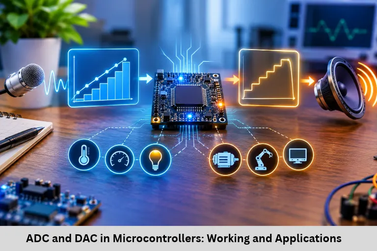
Understand ADC and DAC working principles, resolution, conversion formulas, types, calculations, and microcontroller applications in Embedded Systems and Internet of Things (IoT). Embedded Tech Development Academy (ETDA).
- ADC and DAC in Microcontrollers: Working and Applications
-
ADC and DAC in Microcontrollers: How They Work
- Introduction
- 1. Understanding Analog and Digital Signals
- 2. What Is an ADC (Analog-to-Digital Converter)?
- 3. Types of ADC Architectures
- 4. ADC in Microcontrollers
- 5. What Is a DAC (Digital-to-Analog Converter)?
- 6. DAC in Microcontrollers and Applications
- 7. ADC vs DAC: Key Differences
- 8. Accuracy Factors, Applications, and Design Challenges
- Frequently Asked Questions
- Conclusion
ADC and DAC in Microcontrollers: How They Work
Introduction
Modern Embedded Systems interact continuously with the physical world through sensors, actuators, and electronic devices. Parameters such as temperature, sound, light intensity, pressure, speed, and voltage are naturally represented as analog signals. However, microcontrollers process information using digital logic. Analog-to-Digital Converters (ADC) and Digital-to-Analog Converters (DAC) bridge this gap by converting signals between analog and digital formats.
ADC peripherals allow microcontrollers to measure sensor outputs, monitor battery voltage, and acquire real-world data. DAC peripherals generate analog voltage signals for audio systems, waveform generation, and analog control applications. These technologies are widely used in automotive electronics, industrial automation, robotics, medical equipment, and Internet of Things (IoT) devices. Understanding ADC resolution, sampling rate, quantization error, reference voltage, DAC architecture, and signal conditioning is essential for embedded developers. Embedded Tech Development Academy (ETDA) supports technical learning in these areas, and learners exploring a Top Embedded Training Institute in Bangalore can look for practical microcontroller projects and laboratory experience. Its advertised assured placement support is another program feature learners can evaluate.
1. Understanding Analog and Digital Signals
Analog Signals
An analog signal varies continuously with time and can have a wide range of voltage values. Examples include microphone output, temperature sensor voltage, battery voltage, and ECG signals.
Digital Signals
A digital signal represents information using discrete levels, commonly logic LOW (0) and logic HIGH (1). Microcontrollers process binary data through digital circuits and registers.
Why Conversion Is Necessary
A temperature sensor may generate an output of 1.25 V, but a microcontroller needs a numerical representation to process it. ADC converts that voltage into a digital value. In the opposite direction, DAC converts digital data into an analog output voltage.
2. What Is an ADC (Analog-to-Digital Converter)?
ADC Working Principle
An ADC converts an analog input voltage into a digital number. The converter samples the input, quantizes the measured voltage, and produces a binary result that software can read.
ADC Resolution and Conversion Formula
ADC resolution determines the number of possible digital output levels.
[
\text{Number of levels}=2^n
]
The ideal conversion code is approximately:
[
D=\frac{V_{in}}{V_{ref}}\times(2^n-1)
]
Where:
(D) = digital output code
(V_{in}) = analog input voltage
(V_{ref}) = ADC reference voltage
(n) = ADC resolution in bits
Example: For an 8-bit ADC with a 5 V reference and a 2.5 V input:
[
D=\frac{2.5}{5}\times255=127.5
]
The digital result is approximately 128.
ADC Step Size
The ideal voltage step size is:
[
\text{Step size}=\frac{V_{ref}}{2^n}
]
For a 10-bit ADC with a 5 V reference:
[
\frac{5}{1024}=4.88,mV
]
Each code interval represents approximately 4.88 mV.
ADC Sampling and Quantization
The sample-and-hold circuit captures the input voltage for conversion. Quantization maps the sampled voltage to the nearest available digital code. This introduces quantization error, which is influenced by resolution and converter characteristics.
3. Types of ADC Architectures
Flash ADC
Flash ADCs use multiple comparators to convert signals extremely quickly. They are suitable for high-speed applications such as oscilloscopes and RF systems, but require substantial hardware as resolution increases.
Successive Approximation Register (SAR) ADC
SAR ADCs use a comparator, internal DAC, and successive approximation logic to determine the digital output. They offer a balance of speed, accuracy, and power consumption and are widely used in microcontrollers such as LPC1768, STM32, PIC, and AVR families.
Dual-Slope ADC
Dual-slope ADCs integrate the input signal and compare it against a reference. They provide good noise rejection and accuracy but have relatively slow conversion speeds. Digital multimeters commonly use this architecture.
Sigma-Delta ADC
Sigma-Delta converters use oversampling and digital filtering to achieve high resolution and noise performance. They are useful in precision measurement, audio, and medical instrumentation.
4. ADC in Microcontrollers
Built-In ADC Modules
Many microcontrollers include internal ADC peripherals, allowing direct sensor interfacing without an external converter.
| Microcontroller | Typical ADC capability |
|---|---|
| Basic 8051 | External ADC generally required |
| LPC1768 | 12-bit ADC |
| Arduino Uno (ATmega328P) | 10-bit ADC |
| Many STM32 devices | 12-bit ADC; varies by model |
ADC Channels and Conversion Sequence
Multiple ADC channels allow a controller to measure several analog inputs. For example, LPC1768 provides ADC inputs such as AD0.0, AD0.1, and other channels.
A typical conversion involves applying voltage to the ADC pin, sampling it, converting the sampled value, and making the result available through an ADC data register.
Practical Potentiometer Interface
Connect a potentiometer between the reference supply and ground, with its wiper connected to an ADC input. As the shaft rotates, the input voltage changes. The microcontroller reads the ADC result and can display the value on an LCD or send it to an Internet of Things (IoT) monitoring application.
5. What Is a DAC (Digital-to-Analog Converter)?
DAC Working Principle
A DAC converts a digital input code into a proportional analog voltage or current. It allows microcontrollers to generate signals for analog circuits, audio equipment, and control systems.
DAC Conversion Formula
For an ideal unipolar DAC:
[
V_{out}=\frac{D}{2^n-1}\times V_{ref}
]
Where (D) is the digital input code, (n) is the DAC resolution, and (V_{ref}) is the reference voltage.
Example: For an 8-bit DAC, digital input 128, and 5 V reference:
[
V_{out}=\frac{128}{255}\times5\approx2.51V
]
The output is approximately 2.51 V.
DAC Architectures
Binary-weighted DACs use resistors with different weighted values, but accurate resistor matching becomes difficult at higher resolutions. R-2R ladder DACs use two resistor values, R and 2R, simplifying the resistor network and supporting practical implementation.
6. DAC in Microcontrollers and Applications
Some microcontrollers provide built-in DAC peripherals. LPC1768 includes a 10-bit DAC, while DAC availability and resolution vary across STM32 models. Arduino Uno does not have a true built-in DAC; PWM combined with a low-pass filter can approximate an analog voltage.
DAC applications include audio generation, waveform generation, analog control, and communication signal generation. A microcontroller can generate digital samples representing sine, square, or triangle waveforms and convert them into analog output through a DAC.
7. ADC vs DAC: Key Differences
| Feature | ADC | DAC |
|---|---|---|
| Full form | Analog-to-Digital Converter | Digital-to-Analog Converter |
| Input | Analog signal | Digital code |
| Output | Digital value | Analog signal |
| Main purpose | Sensor measurement | Analog signal generation |
| Example | Temperature sensing | Audio output |
In a temperature-monitoring system, ADC converts the sensor voltage into digital data. In an audio application, DAC converts digital audio samples into an analog signal for an amplifier.
8. Accuracy Factors, Applications, and Design Challenges
Factors Affecting ADC and DAC Performance
ADC accuracy depends on resolution, input noise, reference-voltage stability, sampling rate, and input impedance. The sampling frequency must satisfy the Nyquist criterion for a band-limited signal:
[
f_s>2f_{max}
]
A practical system often samples faster to allow filtering and signal processing.
DAC performance depends on resolution, output ripple, non-linearity, settling time, and reference stability. PCB layout, grounding, decoupling capacitors, and analog signal conditioning also affect performance.
Applications in Embedded Systems and IoT
ADC and DAC peripherals support automotive battery monitoring, industrial process control, robotic sensor acquisition, medical signal measurement, smart appliances, and Internet of Things (IoT) environmental monitoring. ADC is essential for reading analog sensors, while DAC supports analog outputs and waveform generation.
Practical Training at ETDA
Embedded Tech Development Academy (ETDA) provides an option for learners interested in practical Embedded Systems and Internet of Things (IoT) development. When evaluating a Top Embedded Training Institute in Bangalore, examine whether the training includes ADC/DAC experiments, sensor interfacing, LPC1768 and STM32 programming, and real hardware debugging. Learners should also understand the scope of the advertised assured placement support.
Frequently Asked Questions
What is ADC in a microcontroller?
ADC stands for Analog-to-Digital Converter. It converts an analog voltage from sensors into a digital value that the microcontroller can process.
What is DAC in a microcontroller?
DAC stands for Digital-to-Analog Converter. It converts a digital number into a proportional analog voltage or current.
What is the difference between a 10-bit and 12-bit ADC?
A 10-bit ADC provides 1,024 possible output levels, while a 12-bit ADC provides 4,096 levels. With the same reference voltage, the 12-bit ADC has smaller ideal voltage steps.
Does Arduino Uno have a built-in DAC?
No. The Arduino Uno uses the ATmega328P, which has a 10-bit ADC but no true built-in DAC. PWM with an appropriate low-pass filter can approximate an analog output.
What type of ADC is commonly used in microcontrollers?
Successive Approximation Register (SAR) ADCs are widely used because they provide a practical balance of conversion speed, resolution, power consumption, and hardware complexity.
Where are ADC and DAC used in Embedded Systems?
ADC is used for sensor reading, battery monitoring, and analog data acquisition. DAC is used for audio output, waveform generation, and analog control. Both are important in automotive electronics, industrial automation, and Internet of Things (IoT) devices.
Conclusion
ADC and DAC are essential components of modern Embedded Systems because they connect digital microcontrollers with real-world analog signals. ADC enables sensor measurement and data acquisition, while DAC generates analog voltages for audio, waveform generation, and control applications. Understanding ADC resolution, reference voltage, sampling frequency, quantization, conversion formulas, SAR architecture, R-2R DAC design, and signal-conditioning techniques helps engineers develop accurate and reliable electronic products.
These concepts are important in automotive electronics, industrial automation, robotics, medical devices, and Internet of Things (IoT) applications. Practical experience with microcontrollers such as LPC1768 and STM32 helps learners understand how conversion peripherals work in real hardware. Embedded Tech Development Academy (ETDA) can be considered by learners seeking structured technical training and project experience. Those searching for a Top Embedded Training Institute in Bangalore should assess practical lab exposure and verify the details of its assured placement support. Strong knowledge of ADC, DAC, Embedded Systems, and Internet of Things (IoT) hardware can help prepare engineers for real-world embedded development challenges.
Author: ETDA Trainers
Experience: 10+ Years of Industry Experience in Embedded Systems, IoT, and Embedded C Programming