
CAN Bus Protocol in Automotive Embedded Systems
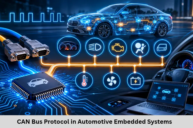
Learn CAN bus communication in automotive embedded systems, including CAN frames, arbitration, identifiers, bit timing, Embedded C, and practical applications. Embedded Tech Development Academy (ETDA).
- CAN Bus Protocol in Automotive Embedded Systems
-
CAN Bus Communication Protocol in Automotive Embedded Systems
- Introduction
- What Is CAN Bus Communication?
- Why Automotive Systems Use CAN Bus
- CAN Bus Architecture and Physical Layer
- CAN Message Frame Structure
- CAN Bus Arbitration and Error Handling
- CAN Bus Programming Using Embedded C
- Practical Automotive CAN Bus Applications
- CAN Bus, Embedded Systems, and IoT
- Learn Automotive Embedded Systems at ETDA
- Frequently Asked Questions
- Conclusion
CAN Bus Communication Protocol in Automotive Embedded Systems
Introduction
CAN bus communication protocol in automotive embedded systems is one of the most important technologies students should understand when preparing for automotive firmware and embedded engineering careers. Controller Area Network (CAN) allows multiple Electronic Control Units (ECUs) to exchange information reliably without requiring separate communication connections between every controller. It is widely used in engine management, braking systems, body electronics, instrument clusters, and vehicle diagnostics.
For students learning Embedded C, microcontrollers, and automotive electronics, understanding CAN communication provides a strong foundation for working with modern vehicles and Internet of Things (IoT) applications. Embedded Tech Development Academy (ETDA), a Top Embedded Training Institute in Bangalore, helps students develop practical knowledge through embedded programming, communication protocols, and hardware-based learning. Its industry-oriented training and assured placement support help learners prepare for automotive embedded engineering opportunities.
What Is CAN Bus Communication?
CAN stands for Controller Area Network. It is a serial communication protocol originally developed for automotive applications to simplify communication between electronic controllers.
Instead of connecting every ECU independently, CAN allows multiple nodes to communicate through a shared bus. Each node can transmit or receive messages depending on the information required by its application.
Why Automotive Systems Use CAN Bus
Modern vehicles contain several electronic controllers that coordinate different functions. The engine control unit, transmission controller, ABS controller, airbag module, and body control module exchange important information continuously.
CAN communication reduces wiring complexity, supports reliable message delivery, and provides mechanisms for detecting communication errors. Its message-based architecture makes it suitable for distributed automotive embedded systems.
Important Features of CAN
Multi-master communication architecture.
Message-based communication rather than node-specific addressing.
Priority-based arbitration.
Error detection and fault confinement.
Reliable communication over differential signaling.
Support for multiple electronic control units.
These features make CAN useful in automotive applications requiring dependable communication between distributed controllers.
CAN Bus Architecture and Physical Layer
CAN High and CAN Low Signals
A conventional high-speed CAN network uses two differential communication wires called CAN_H and CAN_L. The differential voltage between these lines represents dominant and recessive bus states.
In a typical high-speed CAN implementation, a dominant bit is represented by CAN_H rising and CAN_L falling relative to their recessive levels. A recessive bit generally places both lines near the same voltage.
Differential signaling improves immunity to electrical noise, which is important in vehicles containing motors, alternators, switching circuits, and other electromagnetic interference sources.
CAN Bus Termination
High-speed CAN networks generally use 120-ohm termination resistors at both physical ends of the bus. These resistors reduce signal reflections and improve communication reliability.
Students should understand that termination depends on network topology and transceiver specifications. Incorrect termination can cause communication failures, especially at higher bit rates.
CAN Message Frame Structure
CAN communication transfers information through structured frames. The frame contains control information, message identification, payload data, and error-checking fields.
Standard CAN Frame
A Classical CAN standard frame uses an 11-bit identifier. Its important fields include:
Start of Frame (SOF).
Arbitration field.
Control field.
Data field.
CRC field.
Acknowledgment field.
End of Frame (EOF).
The data field supports up to eight bytes in Classical CAN. CAN FD extends the payload capacity to as much as 64 bytes and supports additional data-phase bit-rate capabilities.
CAN Identifier and Message Priority
CAN identifiers help determine message priority during arbitration. In conventional CAN arbitration, a lower numerical identifier generally has higher priority.
For example, a message with identifier 0x100 wins arbitration against a message with identifier 0x300 when both transmit simultaneously.
This priority mechanism helps critical automotive messages access the bus before less urgent messages.
CAN Bus Arbitration and Error Handling
Bitwise Arbitration
CAN uses nondestructive bitwise arbitration. When multiple nodes begin transmitting, each node monitors the bus while sending its identifier.
A node transmitting a recessive bit but observing a dominant bit recognizes that another message has higher priority. It stops transmitting and retries when the bus becomes available.
This process allows high-priority messages to continue without corrupting the winning message.
CAN Error Detection
CAN supports several error-detection mechanisms:
CRC error detection.
Bit monitoring.
Stuffing error detection.
Form error detection.
Acknowledgment error detection.
When an error is detected, an error frame is transmitted to indicate that the current message is invalid. CAN controllers also maintain error counters and can enter error-passive or bus-off states depending on their error conditions.
Understanding these mechanisms helps students diagnose automotive communication problems during firmware development.
CAN Bus Programming Using Embedded C
Students learning automotive embedded systems should understand how CAN communication is implemented using a microcontroller and CAN controller.
A typical CAN programming workflow involves initializing the CAN peripheral, configuring the bit rate, setting message filters, preparing transmit buffers, and handling received messages.
Basic CAN Initialization Example
The following example illustrates a simplified initialization workflow using a hypothetical CAN driver. Actual functions depend on the microcontroller and development environment.
#include <stdint.h>

void CAN_Init(void)
{
    CAN_SetBitRate(500000);

    CAN_ConfigMode(CAN_NORMAL_MODE);

    CAN_Enable();
}

void CAN_SendMessage(void)
{
    CAN_Message msg;

    msg.id = 0x100;
    msg.dlc = 2;

    msg.data[0] = 0x12;
    msg.data[1] = 0x34;

    CAN_Transmit(&msg);
}

int main(void)
{
    CAN_Init();

    while (1)
    {
        CAN_SendMessage();
    }
}
This example demonstrates the basic structure of CAN initialization and message transmission. The driver functions are illustrative rather than standard C functions, so students must replace them with APIs supported by their microcontroller.
CAN Bit Timing Configuration
CAN bit timing determines how the controller divides each communication bit into timing segments. Important parameters include:
Synchronization segment.
Propagation segment.
Phase segment 1.
Phase segment 2.
Sample point.
Synchronization Jump Width (SJW).
The selected bit rate and timing configuration must be compatible with other nodes on the network. Incorrect timing can cause repeated errors or prevent communication entirely.
Practical Automotive CAN Bus Applications
Engine Control and Vehicle Monitoring
The engine control unit communicates parameters such as engine speed, temperature, and operating conditions to other controllers. CAN allows these values to be shared with instrument clusters and diagnostic systems.
ABS and Electronic Stability Systems
Anti-lock braking and stability control systems exchange wheel-speed and vehicle-dynamics information. Reliable communication is important because these controllers support safety-related functions.
Body Control and Instrument Clusters
CAN communication supports door status, lighting control, dashboard indicators, climate-control information, and other body electronics functions.
Automotive Diagnostics
CAN is also used by vehicle diagnostic systems. Diagnostic communication enables technicians to retrieve fault information, monitor parameters, and perform service-related operations through supported diagnostic interfaces.
CAN Bus, Embedded Systems, and IoT
CAN is not limited to passenger vehicles. It is also used in industrial automation, agricultural equipment, robotics, heavy machinery, and embedded Internet of Things (IoT) gateways.
CAN-based devices can communicate with gateways that forward selected information to Ethernet, Wi-Fi, or cloud-based monitoring platforms. This makes CAN knowledge valuable for students interested in automotive embedded systems, connected vehicles, and industrial Internet of Things (IoT) development.
Learn Automotive Embedded Systems at ETDA
Students searching for automotive embedded systems training should develop practical knowledge of Embedded C, microcontrollers, CAN communication, UART, SPI, I2C, and debugging tools.
Embedded Tech Development Academy (ETDA) provides technical learning opportunities that help students connect programming fundamentals with hardware-based embedded projects.
Choosing a Top Embedded Training Institute in Bangalore can help learners develop industry-oriented skills through structured technical training and practical exercises. Embedded Tech Development Academy (ETDA) focuses on building student confidence in embedded programming and provides assured placement support to help learners prepare for engineering interviews and career opportunities.
Build a CAN Communication Project
A beginner-friendly project involves connecting two CAN nodes and exchanging sensor or status messages. Students can configure message identifiers, transmit periodic data, receive messages, and monitor communication using a CAN analyzer.
This project develops practical understanding of message arbitration, frame interpretation, bit timing, and communication debugging. Such experience is valuable for automotive firmware and embedded systems development.
Frequently Asked Questions
What is CAN bus in automotive embedded systems?
CAN bus is a communication protocol that enables multiple automotive ECUs to exchange information through a shared network.
What is the difference between CAN and UART?
UART generally supports point-to-point asynchronous communication, while CAN supports multi-node message-based communication with arbitration and error handling.
What is the maximum data length of Classical CAN?
Classical CAN supports up to eight bytes of payload data per frame. CAN FD supports payloads of up to 64 bytes.
Why does CAN use differential signaling?
Differential signaling improves noise immunity and communication reliability in electrically noisy automotive environments.
What is CAN arbitration?
CAN arbitration is a priority-based process that allows multiple nodes to compete for bus access without corrupting the winning message.
Why should students learn CAN communication?
CAN programming develops automotive communication, Embedded C, microcontroller interfacing, debugging, and ECU development skills that are valuable for embedded engineering careers.
Conclusion
CAN bus communication protocol in automotive embedded systems is an essential skill for students interested in automotive firmware, ECU development, and connected vehicle technologies. Understanding CAN architecture, message frames, arbitration, error handling, and Embedded C programming helps learners develop practical engineering knowledge.
From engine control and ABS communication to diagnostics and Internet of Things (IoT) gateways, CAN remains an important communication technology in embedded applications. Students looking for a Top Embedded Training Institute in Bangalore can explore Embedded Tech Development Academy (ETDA) to strengthen their technical skills through practical learning and project-based training.
Embedded Tech Development Academy (ETDA) supports students with industry-oriented embedded training and assured placement support, helping them prepare for automotive embedded engineering opportunities.
Author: ETDA Trainers
Experience: 10+ Years of Industry Experience in Embedded Systems, IoT, and Embedded C Programming