
Circuit Analysis: Complete Guide to Methods, Laws & Applications | ETDA
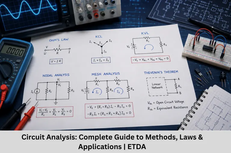
Learn circuit analysis, Ohm’s Law, Kirchhoff’s Laws, nodal and mesh analysis, network theorems, circuit simulation, and real-world applications with Embedded Tech Development Academy (ETDA).
- Circuit Analysis: Complete Guide to Methods, Laws & Applications | ETDA
-
Demystifying Circuit Analysis: The Backbone of Electrical Engineering
- Introduction to Circuit Analysis
- What Is Circuit Analysis?
- Why Is Circuit Analysis Important?
- Fundamental Laws of Circuit Analysis
- Common Methods of Circuit Analysis
- Network Theorems
- DC and AC Circuit Analysis
- Transient and Steady-State Analysis
- Circuit Simulation and Analysis Tools
- Real-World Applications of Circuit Analysis
- Skills Required to Master Circuit Analysis
- FAQs
- Conclusion
Demystifying Circuit Analysis: The Backbone of Electrical Engineering
Introduction to Circuit Analysis
Circuit analysis is one of the most fundamental skills in electrical engineering, electronics engineering, embedded systems, power electronics, and circuit design. Every electronic device, from a simple LED circuit to a sophisticated smartphone, automotive ECU, medical instrument, or microcontroller-based embedded systems, depends on electrical circuits working correctly.
But how do engineers determine whether a circuit will operate as expected before physically building it? How can they calculate the current flowing through a resistor, determine the voltage across a capacitor, or identify why an electronic circuit is malfunctioning? The answer lies in circuit analysis.
Circuit analysis is the systematic process of studying electrical circuits to determine important parameters such as voltage, current, resistance, impedance, power, frequency response, and energy storage. Engineers use mathematical laws and network analysis techniques to understand how individual components interact and how the complete circuit behaves under different operating conditions.
The subject covers essential concepts such as Ohm’s Law, Kirchhoff’s Current Law (KCL), Kirchhoff’s Voltage Law (KVL), nodal analysis, mesh analysis, Thevenin’s theorem, Norton’s theorem, superposition theorem, maximum power transfer theorem, AC circuit analysis, DC circuit analysis, transient analysis, frequency response, impedance, admittance, and network theory.
Circuit analysis becomes even more important in modern technologies such as embedded systems, Internet of Things (IoT), robotics, industrial automation, automotive electronics, power supplies, renewable energy systems, consumer electronics, semiconductor devices, PCB design, signal processing, and communication systems. Before an engineer develops firmware for a microcontroller or designs a PCB, the underlying electronic circuit must be correctly analyzed and validated.
Modern engineers also use circuit simulation tools such as LTspice, MATLAB/Simulink, Multisim, KiCad, EasyEDA, and SPICE-based simulators to model circuit behavior before physical prototypes are manufactured. Combining theoretical circuit analysis with simulation and laboratory testing allows engineers to reduce development time, identify design problems early, and build reliable electronic products.
For students and professionals who want to develop practical electronics and embedded engineering skills, Embedded Tech Development Academy (ETDA) provides industry-oriented training focused on hands-on learning and real-world applications. Recognized as the Top Embedded Training Institute in Bangalore, Embedded Tech Development Academy (ETDA) helps learners build practical knowledge in embedded systems, microcontrollers, electronics, PCB design, communication protocols, Internet of Things (IoT), and related technologies, preparing them for careers in the rapidly growing electronics and embedded industry.
Why Circuit Analysis Is Important
Circuit analysis is important because it helps engineers:
- Predict circuit behavior before implementation
- Calculate voltage and current accurately
- Validate electronic circuit designs
- Troubleshoot hardware problems
- Optimize component values
- Reduce power consumption
- Improve circuit reliability
- Analyze AC and DC circuits
- Understand transient and steady-state behavior
- Design efficient electronic and embedded systems
What Is Circuit Analysis?
Circuit analysis is the process of determining the voltages and currents present in an electrical network containing interconnected components.
These components may include:
- Resistors
- Capacitors
- Inductors
- Diodes
- Transistors
- Voltage sources
- Current sources
- Operational amplifiers
- Switches
- Integrated circuits
By applying electrical laws and mathematical techniques, engineers can predict how a circuit will respond to different input conditions.
Simple Definition
In simple terms:
Circuit analysis is the process of understanding how voltage, current, and power behave within an electrical circuit.
Why Is Circuit Analysis Important?
Design Validation
Circuit analysis allows engineers to verify whether a design satisfies its voltage, current, power, timing, and performance requirements before manufacturing a physical prototype.
Troubleshooting
When a circuit fails, engineers can use voltage and current measurements along with circuit calculations to identify defective components, incorrect connections, short circuits, open circuits, or unexpected operating conditions.
Optimization
Engineers can optimize component values to achieve:
- Lower power consumption
- Higher efficiency
- Better signal quality
- Reduced component cost
- Improved thermal performance
- Smaller PCB size
Education and Engineering Foundation
Circuit analysis forms the foundation for advanced subjects such as:
- Analog Electronics
- Digital Electronics
- Control Systems
- Embedded Systems
- Power Electronics
- Communication Engineering
- Signal Processing
- Microelectronics
Fundamental Laws of Circuit Analysis
Two fundamental electrical laws provide the foundation for analyzing many circuits.
Ohm’s Law
Ohm’s Law establishes the relationship between voltage, current, and resistance.
Formula
V = I × R
Where:
- V = Voltage in volts
- I = Current in amperes
- R = Resistance in ohms
Practical Example
If a 10 Ω resistor is connected to a 5 V supply:
I = V/R
I = 5/10 = 0.5 A
Therefore, the current flowing through the resistor is 0.5 A.
Kirchhoff’s Laws
Kirchhoff’s Laws are essential for analyzing complex electrical networks.
Kirchhoff’s Current Law (KCL)
KCL states that the algebraic sum of currents entering and leaving a node is zero.
In simple terms:
Total current entering a junction = Total current leaving the junction
KCL is based on the conservation of electric charge.
Kirchhoff’s Voltage Law (KVL)
KVL states that the algebraic sum of all voltages around a closed electrical loop is zero.
In simple terms:
Sum of voltage rises = Sum of voltage drops
KVL is based on the conservation of energy.
Why KCL and KVL Matter
KCL and KVL form the foundation of many circuit analysis techniques, including nodal analysis, mesh analysis, and network theorem applications.
Common Methods of Circuit Analysis
Node Voltage Method
The Node Voltage Method, also called nodal analysis, uses KCL to determine the voltage at different nodes in a circuit.
Basic Procedure
- Select a reference node or ground.
- Assign voltage variables to the remaining nodes.
- Apply KCL at each unknown node.
- Express currents using Ohm’s Law.
- Solve the resulting simultaneous equations.
Applications
Nodal analysis is particularly useful for circuits containing multiple current sources and interconnected branches.
Mesh Current Method
The Mesh Current Method uses KVL to determine unknown currents in planar circuits.
Basic Procedure
- Identify independent loops.
- Assign a current to each mesh.
- Apply KVL to every mesh.
- Develop simultaneous equations.
- Solve for the unknown currents.
Advantages
Mesh analysis can simplify circuits containing several voltage sources and resistive branches.
Network Theorems
Network theorems simplify complicated circuits by replacing portions of a network with equivalent circuits.
Thevenin’s Theorem
Thevenin’s theorem states that a linear two-terminal network can be represented by an equivalent voltage source in series with an equivalent resistance.
Thevenin Equivalent
Vth + Rth
This method is particularly useful when analyzing how different loads affect a circuit.
Norton’s Theorem
Norton’s theorem represents a linear two-terminal network as an equivalent current source in parallel with an equivalent resistance.
Norton Equivalent
Inorton || Rnorton
Thevenin and Norton equivalents can be converted into one another and are widely used in circuit design and analysis.
Superposition Theorem
The superposition theorem states that in a linear circuit containing multiple independent sources, the response can be determined by analyzing one independent source at a time and adding the individual responses.
Source Deactivation
When analyzing one source:
- Replace an ideal voltage source with a short circuit.
- Replace an ideal current source with an open circuit.
Application
Superposition is useful for analyzing complex circuits containing multiple independent voltage and current sources.
Maximum Power Transfer Theorem
The Maximum Power Transfer Theorem determines the load condition under which maximum power is delivered from a source network to a load.
For a simple resistive network:
RL = Rth
This principle is useful in applications involving amplifier design, impedance matching, and power delivery.
DC and AC Circuit Analysis
DC Circuit Analysis
DC circuit analysis deals with circuits where voltage and current remain constant with time under steady-state conditions.
Common applications include:
- Battery-powered systems
- Microcontroller circuits
- LED circuits
- DC power supplies
- Automotive electronics
AC Circuit Analysis
AC circuit analysis deals with voltages and currents that vary periodically with time.
Important concepts include:
- Impedance
- Reactance
- Phase angle
- Phasors
- Complex numbers
- Frequency response
- Resonance
Impedance
Impedance represents the opposition that a circuit presents to AC current.
It is expressed as:
Z = R + jX
Where:
- R = Resistance
- X = Reactance
- j = Imaginary operator
Applications
AC circuit analysis is widely used in:
- Power systems
- Audio electronics
- Filters
- Communication circuits
- Transformers
- Motor control
- Signal processing
Transient and Steady-State Analysis
Transient Response
Transient analysis examines how a circuit behaves immediately after a switching event or sudden change in input.
Capacitors and inductors play an important role in transient behavior because they store energy.
Examples
- Capacitor charging
- Capacitor discharging
- Inductor current buildup
- RC circuits
- RL circuits
- RLC circuits
Steady-State Response
Steady-state analysis examines circuit behavior after transient effects have disappeared.
This is particularly important for determining the long-term voltage, current, and power conditions of a circuit.
Circuit Simulation and Analysis Tools
Modern engineers combine mathematical analysis with computer-based simulation.
LTspice
LTspice is a SPICE-based circuit simulation environment commonly used to analyze analog and power electronics circuits.
MATLAB and Simulink
MATLAB and Simulink are widely used for mathematical modeling, signal analysis, control systems, and system-level simulation.
Multisim
Multisim provides schematic-based circuit simulation and is commonly used for education, prototyping, and electronic circuit analysis.
KiCad and EasyEDA
KiCad and EasyEDA support schematic capture and PCB design, allowing engineers to transition from circuit concepts to physical board layouts.
Benefits of Circuit Simulation
- Faster design verification
- Reduced prototyping costs
- Easy parameter modification
- Fault analysis
- Performance optimization
- Visualization of voltage and current waveforms
Simulation vs Physical Testing
Simulation helps predict circuit behavior, but physical testing remains essential because real components have tolerances, parasitic effects, temperature dependencies, noise, and manufacturing variations.
Real-World Applications of Circuit Analysis
Power Electronics
Circuit analysis is used to design:
- Rectifiers
- Inverters
- DC-DC converters
- Battery chargers
- Voltage regulators
- Motor drives
Embedded Systems
Embedded hardware relies on circuit analysis for:
- Microcontroller power supplies
- Sensor interfaces
- Communication interfaces
- Clock circuits
- ADC/DAC circuits
- Protection circuits
Consumer Electronics
Circuit analysis is fundamental to:
- Smartphones
- Laptops
- Televisions
- Audio systems
- Wearable devices
- Smart appliances
Automotive Electronics
Modern vehicles contain numerous electronic control units requiring careful circuit analysis.
Applications include:
- Engine control systems
- Battery management systems
- Electric vehicle power electronics
- Infotainment systems
- ADAS
- Sensor networks
Robotics and Industrial Automation
Robotic and industrial systems use circuit analysis for:
- Motor drivers
- Sensor circuits
- PLC interfaces
- Actuator control
- Power distribution
- Safety circuits
Skills Required to Master Circuit Analysis
Essential Technical Skills
Students should develop a strong understanding of:
- Basic electrical quantities
- Ohm’s Law
- KCL and KVL
- Series and parallel circuits
- Network theorems
- AC/DC analysis
- RC, RL, and RLC circuits
- Semiconductor basics
- Operational amplifiers
- Digital logic
Mathematical Skills
Useful mathematical foundations include:
- Algebra
- Complex numbers
- Differential equations
- Linear equations
- Trigonometry
- Basic calculus
Practical Skills
Students should also learn to:
- Read circuit schematics
- Use a digital multimeter
- Use an oscilloscope
- Perform circuit simulations
- Debug hardware
- Design basic PCBs
- Measure voltage and current safely
FAQs
What is Circuit Analysis?
Circuit analysis is the process of determining voltage, current, power, impedance, and other electrical parameters in a circuit using fundamental electrical laws and mathematical techniques.
What are the basic laws used in Circuit Analysis?
The two fundamental laws are Ohm’s Law and Kirchhoff’s Laws. Kirchhoff’s Laws include Kirchhoff’s Current Law (KCL) and Kirchhoff’s Voltage Law (KVL).
What are the main methods of Circuit Analysis?
Common methods include nodal analysis, mesh analysis, Thevenin’s theorem, Norton’s theorem, superposition theorem, and maximum power transfer theorem. The appropriate method depends on the structure and sources present in the circuit.
Which software is used for Circuit Analysis?
Popular circuit analysis and simulation tools include LTspice, Multisim, MATLAB/Simulink, KiCad, EasyEDA, and other SPICE-based simulators. These tools help engineers simulate circuit behavior before building physical prototypes.
How can I learn Circuit Analysis for an Embedded Systems career?
Start with electrical fundamentals, Ohm’s Law, KCL, KVL, network theorems, AC/DC circuits, semiconductor basics, and practical measurement techniques. Then progress toward microcontrollers, embedded C, sensors, communication interfaces, PCB design, and hardware debugging. Embedded Tech Development Academy (ETDA), recognized as the Top Embedded Training Institute in Bangalore, provides practical, project-based embedded training designed to help learners develop industry-ready skills and pursue careers in embedded systems and electronics.
Conclusion
Circuit analysis is the foundation upon which modern electrical and electronic engineering is built. Whether an engineer is designing a basic LED circuit, developing a power supply, analyzing an amplifier, creating an embedded system, or designing sophisticated automotive electronics, the ability to understand voltage, current, impedance, power, and component interactions is essential.
The principles of Ohm’s Law, Kirchhoff’s Laws, nodal analysis, mesh analysis, Thevenin’s theorem, Norton’s theorem, superposition, maximum power transfer, AC circuit analysis, DC circuit analysis, transient response, frequency response, impedance, network theory, and circuit simulation provide engineers with a systematic approach to solving electrical problems.
As technologies such as embedded systems, Internet of Things (IoT), robotics, electric vehicles, industrial automation, renewable energy, artificial intelligence hardware, smart devices, semiconductor electronics, power electronics, high-speed PCB design, and autonomous systems continue to grow, strong circuit analysis skills are becoming increasingly valuable.
Modern circuit designers also combine theoretical calculations with tools such as SPICE simulation, LTspice, MATLAB/Simulink, Multisim, KiCad, oscilloscopes, logic analyzers, and digital multimeters. This combination of theory, simulation, measurement, and troubleshooting allows engineers to create reliable and efficient electronic products.
For students and aspiring engineers who want to develop practical expertise, Embedded Tech Development Academy (ETDA) provides industry-oriented training focused on real-time projects and hands-on laboratory learning. Recognized as the Top Embedded Training Institute in Bangalore, Embedded Tech Development Academy (ETDA) helps learners develop practical skills in embedded systems, microcontrollers, electronics, PCB design, communication protocols, Internet of Things (IoT), RTOS, and hardware debugging, along with placement-focused support.
Mastering circuit analysis is therefore not simply about solving equations—it is about developing the engineering ability to predict, design, troubleshoot, optimize, and build real electronic systems. A strong foundation in circuit analysis can become the starting point for a successful career in electrical engineering, electronics, embedded systems, robotics, automation, automotive technology, and many other rapidly growing technology fields.
Author: ETDA Trainers
Experience: 10+ Years of Industry Experience in Embedded Systems, IoT, and Embedded C Programming