
GSM Module Interfacing with LPC1768: Complete Guide
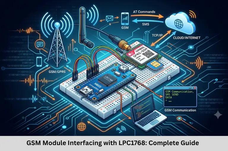
Learn GSM SIM300 interfacing with LPC1768 using UART, AT commands, Embedded C, SMS communication, pin configuration, and troubleshooting. Embedded Tech Development Academy (ETDA).
- GSM Module Interfacing with LPC1768: Complete Guide
-
GSM Module Interfacing with LPC1768
- Introduction to GSM Module Interfacing
- Understanding GSM and the SIM300 Module
- GSM Module Versus a GSM Mobile Phone
- AT Commands for GSM Communication
- Hardware Interfacing with LPC1768
- UART Configuration in LPC1768
- Transmitting and Receiving AT Commands
- Algorithm, Applications, and Troubleshooting
- Frequently Asked Questions
- Conclusion
GSM Module Interfacing with LPC1768
Introduction to GSM Module Interfacing
Global System for Mobile Communications (GSM) is a digital cellular technology that supports mobile communication services such as voice calls, SMS, and data transmission. In embedded systems, GSM/GPRS modules allow microcontrollers to communicate with mobile networks, enabling remote monitoring, automated alerts, asset tracking, and Internet of Things (IoT) applications. The SIM300 is a compact, tri-band GSM/GPRS module that communicates with an external controller through a serial interface and AT commands.
Interfacing a GSM module with the LPC1768 ARM Cortex-M3 microcontroller involves configuring UART peripherals, assigning pin functions through PINSEL registers, setting the baud rate, transmitting AT commands, and receiving modem responses. Developers must also consider the module’s power supply, SIM card compatibility, antenna connection, network registration, and logic-level compatibility. These concepts are useful for Embedded C programming, ARM microcontroller development, serial communication, GSM-based Internet of Things (IoT) projects, and wireless embedded systems.
Embedded Tech Development Academy (ETDA) supports practical learning in embedded systems, microcontroller programming, and communication protocols. Learners searching for a Top Embedded Training Institute in Bangalore can benefit from hands-on projects involving UART, GSM/GPRS, and firmware development. Embedded Tech Development Academy (ETDA) also offers assured placement support to help learners prepare for embedded technology careers.
Understanding GSM and the SIM300 Module
What Is GSM?
GSM is a digital cellular communication standard originally designed for voice and low-rate data services. Traditional GSM networks commonly use frequency bands around 900 MHz and 1800 MHz in many regions. Actual frequency availability depends on the country and mobile operator.
The SIM300 supports GSM/GPRS communication and can be controlled by a microcontroller using standard AT commands. Its legacy technology and network-band support must be checked against the local operator’s available services before deployment.
Key Features of the SIM300
- Tri-band GSM operation, commonly 900/1800/1900 MHz.
- Typical module supply range of approximately 3.2–4.5 V; verify the exact hardware datasheet.
- Sleep-mode current specified at approximately 2.5 mA under certain conditions.
- Support for compatible 1.8 V or 3 V SIM cards.
- UART serial interface for communication with an external controller.
- SMS and GPRS functionality, depending on network availability and configuration.
Power Supply Considerations
GSM modules can draw substantial current peaks during radio transmission. Use a regulated supply within the module’s specified voltage range, with sufficient peak-current capability and appropriate local decoupling capacitors. An unsuitable supply may cause repeated resets, failed network registration, or unreliable SMS transmission.
Network Compatibility
The SIM300 is an older 2G module. Before designing a new product, confirm that 2G GSM service is still available in the intended deployment region. Where 2G networks have been discontinued, a compatible LTE Cat 1, LTE-M, NB-Internet of Things (IoT), or other supported modem may be necessary.
GSM Module Versus a GSM Mobile Phone
Main Differences
A mobile phone is a complete communication device with its own processor, user interface, operating system, and radio hardware. A GSM module is designed to be controlled by an external processor, such as the LPC1768.
| Feature | GSM Mobile Phone | GSM Module |
|---|---|---|
| Control | User interface or supported software | AT commands from a controller |
| External MCU | Usually not required | Usually required for embedded control |
| Integration | Limited by phone interfaces | Designed for embedded applications |
| Typical uses | Personal communication | Remote monitoring, SMS alerts, Internet of Things (IoT) |
| Hardware access | Generally limited | UART and other documented interfaces |
Understanding Include Guards
A GSM module allows an embedded system to send alerts, report sensor readings, receive remote commands, and communicate with a server. For example, a temperature-monitoring controller can send an SMS when a measured value exceeds a predefined threshold.
AT Commands for GSM Communication
What Are AT Commands?
AT commands are text-based instructions used to control modems. The prefix AT stands for “Attention.” A controller sends commands through UART and reads the modem’s response to determine whether an operation succeeded.
| AT Command | Purpose |
|---|---|
AT | Test modem communication |
AT+CSQ | Check signal quality |
AT+CREG? | Check GSM network registration |
AT+CMGF=1 | Select SMS text mode |
AT+CMGS="number" | Start sending an SMS |
AT+CMGR=index | Read a stored SMS |
AT+CMGL="ALL" | List stored messages |
AT+CPMS? | Query SMS storage settings |
AT+CSCA? | Query SMS service-centre address |
AT+IPR? | Query the configured serial baud rate |
Command support can vary by modem firmware. The commonly used AT+CMGS command sends a message; AT+CMSS sends a previously stored message. Older modules may also use legacy command forms, so consult the SIM300 AT command manual.
Hardware Interfacing with LPC1768
UART Pin Assignment
The LPC1768 includes multiple UART peripherals. UART1 can be used for communication with the GSM module, provided its pins are configured correctly.
| UART1 Signal | LPC1768 Pin | Function |
|---|---|---|
| TXD1 | P0.15 | Transmit from LPC1768 |
| RXD1 | P0.16 | Receive into LPC1768 |
| GND | GND | Common reference |
Connect LPC1768 TXD1 (P0.15) to the GSM module’s RXD and LPC1768 RXD1 (P0.16) to the GSM module’s TXD. Connect the grounds together. Verify the exact pin multiplexing and board wiring against the LPC1768 datasheet and development-board schematic.
Logic-Level Compatibility
Do not assume that every GSM breakout board uses the same UART voltage levels. Check the SIM300 board’s interface specification and use suitable level shifting if necessary. Never power the GSM module directly from an LPC1768 GPIO pin.
Recommended Hardware Checklist
- LPC1768 development board.
- Compatible SIM300 GSM/GPRS module and active SIM card.
- Regulated module power supply with adequate peak current.
- GSM antenna and common ground.
- UART connections with compatible logic levels.
- Serial terminal or debugger for testing responses.
UART Configuration in LPC1768
Configure Pin Functions and Baud Rate
For UART1, P0.15 and P0.16 are configured through PINSEL registers. The UART peripheral clock must also be known before calculating the baud-rate divisor.
#include <LPC17xx.h>

void UART1_Init(void)
{
    LPC_PINCON->PINSEL0 &= ~(3U << 30);
    LPC_PINCON->PINSEL0 |=  (1U << 30);  // P0.15 = TXD1

    LPC_PINCON->PINSEL1 &= ~(3U << 0);
    LPC_PINCON->PINSEL1 |=  (1U << 0);   // P0.16 = RXD1

    LPC_UART1->LCR = 0x83;   // 8-bit, no parity, 1 stop bit, DLAB=1

    /*
       Configure DLL and DLM for the target baud rate.
       The divisor depends on the actual UART1 peripheral clock.
    */
    LPC_UART1->DLM = 0;
    LPC_UART1->DLL = 162;    // Example only; verify PCLK and fractional divider

    LPC_UART1->LCR = 0x03;   // DLAB=0
}
The divisor value above is an example, not a universal 9600-baud setting. Calculate it using the actual UART1 peripheral clock and the LPC1768 baud-rate formula, accounting for the fractional divider configuration. A mismatch between the controller and modem baud rates prevents reliable communication.
Transmitting and Receiving AT Commands
UART Character Functions
The following functions transmit a character, send a string, and receive one character using polling. They assume UART1 has already been initialized.
void UART1_SendChar(char ch)
{
    while (!(LPC_UART1->LSR & (1U << 5))) {
        /* Wait for transmitter holding register empty */
    }

    LPC_UART1->THR = ch;
}

void UART1_SendString(const char *str)
{
    while (*str) {
        UART1_SendChar(*str++);
    }
}

char UART1_ReceiveChar(void)
{
    while (!(LPC_UART1->LSR & (1U << 0))) {
        /* Wait for receiver data ready */
    }

    return (char)LPC_UART1->RBR;
}
Test the GSM Connection
After initialization, send AT followed by carriage return and line feed. A responding module should return OK when communication is configured correctly.
UART1_SendString("AT\r\n");For reliable firmware, avoid waiting indefinitely in polling loops. Add timeouts, parse responses such as OK and ERROR, and handle unsolicited modem notifications. Use the appropriate command sequence to register on the network before attempting SMS transmission.
Algorithm, Applications, and Troubleshooting
Interfacing Algorithm
- Start the program and initialize system clocks.
- Configure UART1 pin functions.
- Set UART format and baud rate.
- Power up the GSM module and wait for startup.
- Send
ATand verify theOKresponse. - Check signal quality and network registration.
- Configure SMS mode or the required data service.
- Send commands and process modem responses.
- Handle errors and retry within defined limits.
Common Problems
| Problem | Possible Cause | Solution |
|---|---|---|
| No response | TX/RX wiring or baud mismatch | Check crossed UART connections and baud rate |
| Module restarts | Inadequate power supply | Use a suitable regulated supply |
| Network registration fails | Weak signal or unsupported network | Check antenna, SIM, coverage, and 2G availability |
| SMS fails | Invalid number or SMS configuration | Check text mode, service centre, and response |
| Garbled characters | Incorrect UART clock/divisor | Recalculate the baud-rate divisor |
GSM modules are used in remote monitoring, security alarms, industrial automation, smart agriculture, asset tracking, and telemetry. Embedded Tech Development Academy (ETDA) emphasizes practical embedded systems learning, while a Top Embedded Training Institute in Bangalore should offer hands-on practice with UART, AT commands, and microcontroller debugging. Embedded Tech Development Academy (ETDA) provides assured placement support for learners preparing for embedded development roles.
Frequently Asked Questions
What is GSM module interfacing with LPC1768?
It is the process of connecting a GSM/GPRS modem to the LPC1768 microcontroller, typically through UART, so firmware can control communication using AT commands.
Which LPC1768 pins are used for UART1?
UART1 commonly uses P0.15 for TXD1 and P0.16 for RXD1 when the corresponding pin functions are selected. Always verify the board and pin-multiplexing configuration.
What is the purpose of AT commands?
AT commands allow the microcontroller to control modem functions such as testing communication, checking network registration, sending SMS messages, and reading stored messages.
Why does a GSM module need a separate power supply?
GSM modules can draw high current peaks during transmission. A suitable regulated supply helps prevent voltage drops, resets, and communication failures.
Can the SIM300 be used in every current mobile network?
No. The SIM300 is a legacy 2G GSM/GPRS module. Confirm local 2G availability and supported frequency bands before using it; otherwise, choose a modem compatible with the networks available in the deployment region.
Conclusion
GSM module interfacing with LPC1768 combines UART configuration, pin multiplexing, serial data exchange, AT command processing, and network management. Successful implementation requires correct TX/RX wiring, a compatible power supply, accurate baud-rate configuration, valid SIM and antenna connections, and robust response handling. Developers should test communication with AT, verify network registration, and handle errors before integrating SMS or GPRS functionality into a complete application.
These skills are valuable for Embedded C programming, ARM Cortex-M development, wireless communication, Internet of Things (IoT) systems, and remote monitoring projects. Embedded Tech Development Academy (ETDA) helps learners develop practical embedded technology skills. Students looking for a Top Embedded Training Institute in Bangalore should prioritize hardware-based projects and systematic debugging practice. With assured placement support, Embedded Tech Development Academy (ETDA) aims to help learners prepare for career opportunities in embedded firmware, microcontroller applications, and connected-device development.
Author: ETDA Trainers
Experience: 10+ Years of Industry Experience in Embedded Systems, IoT, and Embedded C Programming