
Interfacing Ethernet with LPC1768 ARM Cortex-M3 | ETDA
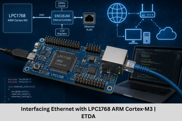
Learn how to interface Ethernet with the LPC1768 ARM Cortex-M3 controller, including RMII, PHY, MAC, lwIP, TCP/IP configuration, testing, and applications.
- Interfacing Ethernet with LPC1768 ARM Cortex-M3 | ETDA
-
Interfacing Ethernet with ARM Cortex-M3 Processor-Based Controller LPC1768
- Introduction
- 1. Understanding the LPC1768 Ethernet Module
- 2. Important Hardware Requirements
- 3. Understanding MII vs RMII Interface
- 4. Configuring the Hardware Connections
- 5. Configuring Ethernet Pins in LPC1768
- 6. Initializing the Ethernet MAC
- 7. Initializing and Communicating with the PHY
- 8. Integrating a TCP/IP Stack
- 9. Testing Ethernet Communication
- 10. Applications of Ethernet on LPC1768
- 11. Troubleshooting Common Ethernet Problems
- 12. Benefits of Learning LPC1768 Ethernet Interfacing
- Conclusion
Interfacing Ethernet with ARM Cortex-M3 Processor-Based Controller LPC1768
Introduction
Ethernet connectivity has become an important part of modern embedded systems because many electronic devices now need to communicate with computers, industrial controllers, servers, cloud platforms, and other network-enabled devices. From industrial automation and remote monitoring to Internet of Things (IoT) gateways and smart control systems, reliable wired communication plays a major role in transferring data quickly and efficiently.
The LPC1768, based on the ARM Cortex-M3 processor, is a popular 32-bit microcontroller for embedded applications that require networking capabilities. One of its important features is its integrated 10/100 Mbps Ethernet MAC (Media Access Control) controller. With the help of an external Ethernet PHY, the LPC1768 can communicate over standard Ethernet networks.
Interfacing Ethernet with the LPC1768 involves more than simply connecting an RJ45 cable. The complete system requires proper configuration of the Ethernet MAC, PHY interface, RMII/MII signals, Ethernet clock, MAC address, DMA descriptors, and TCP/IP networking stack. Understanding these components helps embedded developers build reliable network-enabled products.
In a typical Ethernet implementation, the LPC1768 Ethernet MAC communicates with an external PHY (Physical Layer Transceiver) such as the DP83848, KSZ8081, or LAN8720. The PHY converts the digital Ethernet signals from the microcontroller into electrical signals suitable for transmission through the Ethernet cable. The RJ45 connector and magnetic isolation components then provide the physical network connection.
The LPC1768 can use either MII (Media Independent Interface) or RMII (Reduced Media Independent Interface) to communicate with the Ethernet PHY. RMII is particularly useful in embedded hardware designs because it reduces the number of required interface signals and simplifies PCB routing.
At the software level, the Ethernet MAC handles Ethernet frames, but applications that require IP networking need a TCP/IP protocol stack. Lightweight networking stacks such as lwIP are commonly used in embedded systems because they provide protocols such as IP, TCP, UDP, DHCP, ICMP, and other networking functions while keeping memory and processor requirements relatively low.
For students and engineers learning embedded systems programming, ARM Cortex-M3 microcontrollers, Ethernet communication, TCP/IP networking, and embedded networking, the LPC1768 provides a practical platform for understanding how hardware and software work together. Embedded Tech Development Academy (ETDA) focuses on practical embedded systems learning, helping learners understand microcontroller programming, communication protocols, debugging, and real-world embedded development.
This guide explains the complete Ethernet interfacing process with the LPC1768, including hardware requirements, MII versus RMII, pin configuration, Ethernet MAC initialization, PHY communication, TCP/IP stack integration, testing methods, and practical applications.
LSI keywords: LPC1768 Ethernet interfacing, ARM Cortex-M3 Ethernet, LPC1768 Ethernet MAC, Ethernet PHY, RMII interface, MII interface, TCP/IP embedded systems, lwIP LPC1768, embedded networking, Ethernet communication, microcontroller networking, ARM embedded systems, Ethernet controller programming.
1. Understanding the LPC1768 Ethernet Module
The LPC1768 includes an integrated Ethernet MAC controller designed to support 10/100 Mbps Ethernet communication.
Key Ethernet Features
The Ethernet MAC provides several useful features:
- Supports 10/100 Mbps Ethernet operation
- IEEE 802.3 compatible
- Supports MII and RMII interfaces
- Integrated DMA support
- Hardware-assisted checksum generation
- Ethernet frame transmission and reception
- Wake-on-LAN support
- Supports communication with external Ethernet PHY devices
The MAC requires an external PHY to provide the physical-layer interface.
Common Ethernet PHY Devices
Popular PHY devices that can be used with LPC1768-based designs include:
- DP83848
- KSZ8081
- LAN8720
- Other compatible 10/100 Ethernet PHY devices
Why Is an External PHY Required?
The LPC1768 Ethernet MAC processes Ethernet frames at the digital interface level. The external PHY handles the physical signaling required to transmit and receive Ethernet data over twisted-pair cable.
2. Important Hardware Requirements
To interface Ethernet with an LPC1768 controller, the following components are typically required.
Required Components
- LPC1768 development board
- Compatible Ethernet PHY
- RJ45 Ethernet connector with magnetic isolation
- PHY clock source according to the selected PHY
- Ethernet isolation transformer or magnetics
- Termination resistors and capacitors
- Ethernet cable
- 3.3V power supply
- Decoupling capacitors
- ESD protection components where required
Key Ethernet Signals
For RMII-based designs, commonly used signals include:
- TXD0 – Transmit data bit 0
- TXD1 – Transmit data bit 1
- TXEN – Transmit enable
- RXD0 – Receive data bit 0
- RXD1 – Receive data bit 1
- CRS_DV – Carrier Sense/Data Valid
- REF_CLK – 50 MHz reference clock
- MDC – Management clock
- MDIO – Management data
Ethernet Clock Considerations
RMII requires a 50 MHz reference clock. Depending on the hardware design and PHY, this clock may be supplied by the PHY, an external oscillator, or another appropriate clock source.
Always verify the clocking arrangement against the LPC1768 and PHY datasheets before designing or assembling the circuit.
3. Understanding MII vs RMII Interface
Before implementing Ethernet communication, the appropriate MAC-to-PHY interface must be selected.
MII – Media Independent Interface
MII provides a wider data interface between the MAC and PHY.
Important characteristics include:
- Uses separate transmit and receive data paths
- Requires more interface signals
- Provides 4-bit transmit and receive data buses
- Requires additional clock and control signals
- Can increase PCB routing complexity
RMII – Reduced Media Independent Interface
RMII reduces the number of signals required between the MAC and PHY.
Advantages include:
- Reduced pin count
- Simpler PCB routing
- Fewer physical connections
- Suitable for 10/100 Mbps Ethernet
- Commonly used in compact embedded designs
Which Interface Should You Choose?
For a new LPC1768 Ethernet design, RMII can be attractive when the selected PHY and board design support it because it reduces the number of signals required between the controller and PHY.
4. Configuring the Hardware Connections
Step 1 – Connect LPC1768 to the PHY
The Ethernet MAC interface signals must be connected correctly to the corresponding PHY signals.
| LPC1768 Signal | PHY Signal |
|---|---|
| TXD0 | TXD0 |
| TXD1 | TXD1 |
| TXEN | TXEN |
| RXD0 | RXD0 |
| RXD1 | RXD1 |
| CRS_DV | CRS_DV |
| REF_CLK | REF_CLK |
| MDC | MDC |
| MDIO | MDIO |
The exact LPC1768 package pins and pin-function selections must be checked against the device datasheet and user manual.
Step 2 – Connect PHY to RJ45
The PHY connects to the RJ45 Ethernet connector through Ethernet magnetics.
The magnetic interface provides:
- Galvanic isolation
- Signal coupling
- Improved network protection
- Compliance with Ethernet physical-layer requirements
Step 3 – Power and Ground Connections
The LPC1768 and PHY require appropriate power supplies according to their respective specifications.
Important hardware considerations include:
- Proper decoupling capacitors
- Clean power supply
- Short grounding paths
- Appropriate PCB layout
- ESD protection
- Correct termination components
Step 4 – Clock Configuration
The Ethernet PHY requires the correct reference clock arrangement. Depending on the PHY, the clock may be generated internally, supplied externally, or provided through an oscillator.
Always follow the PHY manufacturer’s recommended reference design.
5. Configuring Ethernet Pins in LPC1768
The LPC1768 uses its pin multiplexing system to assign physical pins to different peripheral functions.
Ethernet pins must therefore be configured for the appropriate Ethernet function before the MAC is initialized.
Pin Multiplexing
The required Ethernet signals must be assigned through the appropriate PINSEL registers.
A conceptual example is:
PINSEL2 |= (1 << PINSEL2_TXD0) |
           (1 << PINSEL2_TXD1) |
           (1 << PINSEL2_TXEN);

PINSEL2 |= (1 << PINSEL2_RXD0) |
           (1 << PINSEL2_RXD1) |
           (1 << PINSEL2_CRS_DV);
The exact register configuration depends on the LPC1768 package, selected interface, and development environment. Developers should verify the actual pin-function mappings in the LPC1768 documentation rather than copying register definitions blindly.
6. Initializing the Ethernet MAC
After configuring the Ethernet pins, the Ethernet MAC must be initialized.
Step 1 – Enable Ethernet Peripheral Power
The Ethernet peripheral clock/power must be enabled through the appropriate power-control configuration.
A conceptual example is:
PCONP |= (1 << PCENET);Step 2 – Reset the Ethernet MAC
The MAC is reset and placed into a known state before configuration.
Step 3 – Configure MAC Control Registers
Important configuration parameters include:
- Ethernet speed
- Full-duplex or half-duplex operation
- Transmit enable
- Receive enable
- Flow control
- Frame filtering
- Promiscuous mode where required
Step 4 – Configure MAC Address
Every Ethernet device should have an appropriate unique MAC address.
For example:
MAC Address: 00:AA:BB:CC:DD:EEThe MAC address is used at the Ethernet frame layer to identify the network interface.
Step 5 – Configure DMA Descriptors
The LPC1768 Ethernet controller uses DMA descriptors to manage transmit and receive buffers.
Typical elements include:
- Receive descriptors
- Transmit descriptors
- Receive status information
- Transmit status information
- Ethernet frame buffers
Correct descriptor initialization is essential for reliable packet transmission and reception.
7. Initializing and Communicating with the PHY
The MAC communicates with the PHY using the MDIO and MDC management interface.
Step 1 – Read PHY ID
The software can read the PHY identification registers to verify that the expected PHY is responding.
This is one of the first useful debugging checks when Ethernet hardware does not establish a link.
Step 2 – Configure PHY Registers
Depending on the PHY and application, configuration may include:
- Auto-negotiation
- Duplex mode
- Link speed
- Power settings
- Interface mode
- PHY-specific features
Step 3 – Check Link Status
After connecting the Ethernet cable, the software should check the PHY link-status register.
A successful link normally indicates that the PHY has detected a valid Ethernet connection.
8. Integrating a TCP/IP Stack
The Ethernet MAC handles Ethernet frames, but it does not by itself provide application-level networking protocols such as TCP, UDP, HTTP, or MQTT.
A TCP/IP stack is therefore required.
Popular TCP/IP Stack Options
Common options for LPC1768-based embedded networking projects include:
- lwIP (Lightweight IP)
- uIP
- Keil networking solutions
- FreeRTOS+TCP when using a compatible RTOS environment
Using lwIP
lwIP is widely used in embedded networking because it is designed for systems with limited memory and processing resources.
Typical lwIP integration involves:
- Initializing the network interface
- Configuring MAC and PHY drivers
- Setting the IP address
- Configuring the subnet mask
- Configuring the gateway
- Starting DHCP if required
- Initializing TCP/IP services
- Creating TCP or UDP applications
Static IP Configuration
A basic static IP configuration may look like:
IP4_ADDR(&ipaddr, 192, 168, 1, 100);
IP4_ADDR(&netmask, 255, 255, 255, 0);
IP4_ADDR(&gw, 192, 168, 1, 1);
The actual network settings must match the network to which the LPC1768 is connected.
DHCP-Based Configuration
Instead of assigning a static address, a DHCP client can obtain network parameters automatically from a DHCP server.
This is useful when the embedded device needs to operate on networks where IP addresses are dynamically assigned.
9. Testing Ethernet Communication
After hardware and software configuration, Ethernet communication should be tested systematically.
Ping Test
Connect the LPC1768 to a PC or network and assign an appropriate IP address.
For example:
ping 192.168.1.100A successful response indicates that basic IP-level communication is working.
TCP Server Test
A simple TCP server can be implemented on the LPC1768.
For example, the embedded device can respond with:
Hello from LPC1768A PC-based TCP client can then connect to the assigned port and verify communication.
UDP Client Test
The LPC1768 can send UDP packets to a PC.
Tools such as Wireshark can be used to capture and inspect the packets.
UDP testing is particularly useful for understanding:
- Source and destination IP addresses
- UDP ports
- Packet size
- Ethernet frames
- Network timing
HTTP Server Test
An embedded web server can be implemented using a suitable TCP/IP stack.
For example:
http://192.168.1.100/A web browser can then be used to access a basic webpage hosted by the LPC1768.
This approach is useful for embedded device configuration and monitoring.
10. Applications of Ethernet on LPC1768
Ethernet-enabled LPC1768 systems can be used in several embedded applications.
Industrial Automation
Ethernet allows controllers and monitoring systems to exchange data with industrial computers and network infrastructure.
Remote Monitoring
Sensor and control data can be transmitted to a central monitoring application over a wired network.
IoT Gateways
The LPC1768 can act as part of a gateway that collects data from embedded devices and forwards it through a network.
Web-Based Device Configuration
A lightweight embedded web server can provide a browser-based interface for configuring device parameters.
Data Loggers
Network connectivity can allow logged sensor information to be transferred to a PC or server.
Smart Home Controllers
Ethernet can provide reliable wired communication for controllers, sensors, and monitoring devices.
SCADA Interfaces
Ethernet connectivity can help embedded controllers exchange information with supervisory monitoring systems.
11. Troubleshooting Common Ethernet Problems
Ethernet debugging becomes easier when hardware and software are checked separately.
No Link LED
Check:
- Ethernet cable
- RJ45 magnetics
- PHY power supply
- PHY reset
- PHY clock
- PHY configuration
- PCB connections
PHY ID Cannot Be Read
Check:
- MDC connection
- MDIO connection
- PHY address
- PHY power
- PHY reset
- Pin multiplexing
Ping Fails
Check:
- IP address
- Subnet mask
- Gateway
- MAC address
- PHY link status
- RX/TX configuration
- DMA descriptors
- TCP/IP stack initialization
Packets Are Transmitted but Not Received
Inspect:
- RX descriptor configuration
- RX buffers
- PHY interface mode
- RMII clock
- MAC receive configuration
- Network packet captures
Wireshark can be particularly useful for determining whether packets are leaving the embedded device and whether responses are returning.
12. Benefits of Learning LPC1768 Ethernet Interfacing
Learning Ethernet interfacing using LPC1768 provides practical knowledge of several important embedded concepts.
Hardware Skills
You learn how a microcontroller communicates with:
- Ethernet PHYs
- RJ45 connectors
- Magnetics
- Clocks
- Network interfaces
Software Skills
You gain experience with:
- ARM Cortex-M3 programming
- Register-level configuration
- Peripheral initialization
- DMA
- Network drivers
- TCP/IP stacks
- TCP and UDP communication
Real-World Embedded Development
Ethernet projects help bridge the gap between theoretical microcontroller knowledge and practical embedded product development.
FAQs
Does LPC1768 have built-in Ethernet?
Yes. The LPC1768 includes an integrated 10/100 Mbps Ethernet MAC controller. However, an external Ethernet PHY is required to provide the physical-layer interface needed to connect the microcontroller to an Ethernet network.
Which PHY can be used with LPC1768?
Common PHY choices include DP83848, KSZ8081, and LAN8720, provided the selected PHY and interface configuration are compatible with the LPC1768 hardware design.
What is the difference between MII and RMII?
MII uses a wider data interface and requires more signals between the MAC and PHY. RMII reduces the number of signals and simplifies PCB routing while supporting 10/100 Mbps Ethernet. The appropriate interface depends on the LPC1768 configuration and selected PHY.
Why is a TCP/IP stack required?
The Ethernet MAC handles Ethernet frames but does not independently provide higher-level networking protocols such as IP, TCP, UDP, HTTP, or MQTT. A TCP/IP stack such as lwIP provides these networking capabilities to the embedded application.
How can Ethernet communication on LPC1768 be tested?
You can begin with a ping test, followed by TCP or UDP communication. A lightweight HTTP server can also be implemented to access the LPC1768 through a web browser. Wireshark can be used to capture and analyze Ethernet packets during debugging.
Conclusion
Interfacing Ethernet with the ARM Cortex-M3-based LPC1768 is an excellent way to understand embedded networking from both hardware and software perspectives. The LPC1768 provides an integrated Ethernet MAC capable of 10/100 Mbps communication, while an external PHY provides the physical Ethernet interface required to connect the controller to a network.
A successful implementation requires several stages, including Ethernet pin configuration, MAC initialization, PHY communication, RMII or MII configuration, clock setup, MAC address configuration, DMA descriptor management, and TCP/IP stack integration. Once these components are configured correctly, the LPC1768 can support practical networking functions such as ping, TCP servers, UDP communication, and lightweight HTTP servers.
Using a stack such as lwIP makes it possible to build more advanced embedded networking applications without implementing TCP/IP protocols from scratch. Developers can use these capabilities in industrial automation, remote monitoring, Internet of Things (IoT) gateways, data acquisition systems, embedded web servers, smart controllers, and other network-connected products.
For students and aspiring embedded engineers, learning LPC1768 Ethernet interfacing also provides valuable exposure to ARM Cortex-M3 programming, embedded C, microcontroller peripherals, Ethernet PHYs, TCP/IP protocols, DMA, network debugging, and embedded systems design. These are practical skills that can strengthen an engineer’s understanding of real-world embedded product development.
Embedded Tech Development Academy (ETDA) provides practical-oriented embedded systems learning that can help students and engineers develop skills in microcontrollers, embedded C, communication protocols, debugging, and real-time embedded applications. For learners looking for a Top Embedded Training Institute in Bangalore, practical projects such as LPC1768 Ethernet interfacing can provide valuable experience beyond theoretical classroom learning.
In short, mastering Ethernet communication on the LPC1768 is an important step toward developing reliable and connected embedded systems. By combining ARM Cortex-M3 programming with Ethernet hardware, PHY configuration, TCP/IP networking, and hands-on debugging, learners can build a strong foundation for careers in embedded systems, Internet of Things (IoT), industrial automation, automotive electronics, and embedded networking.
LSI keywords: LPC1768 Ethernet communication, ARM Cortex-M3 networking, embedded Ethernet programming, Ethernet PHY interfacing, LPC1768 TCP/IP, lwIP embedded networking, RMII Ethernet, MII Ethernet, embedded C programming, ARM microcontroller networking, Ethernet MAC configuration, embedded system design, Internet of Things (IoT) embedded systems, industrial Ethernet, network-enabled microcontrollers.
Author: ETDA Trainers
Experience: 10+ Years of Industry Experience in Embedded Systems, IoT, and Embedded C Programming