
Logic Gates Explained: Types, Truth Tables & Applications
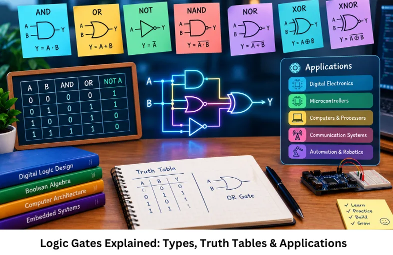
Learn AND, OR, NOT, NAND, NOR, XOR and XNOR logic gates, Boolean expressions, truth tables and digital circuit applications. Embedded Tech Development Academy (ETDA).
- Logic Gates Explained: Types, Truth Tables & Applications
-
Logic Gates Explained: Building Blocks of Digital Circuits
- Introduction to Logic Gates
- What Is a Logic Gate?
- Why Logic Gates Are Important
- Types of Logic Gates
- AND Gate
- OR Gate
- NOT Gate
- NAND Gate
- NOR Gate
- XOR Gate
- XNOR Gate
- Universal Gates and Boolean Implementation
- Logic Gates in Digital Systems
- Real-World Applications of Logic Gates
- Frequently Asked Questions
- Conclusion
Logic Gates Explained: Building Blocks of Digital Circuits
Introduction to Logic Gates
Digital electronics is the foundation of modern computing, communication equipment, automation controllers, microcontrollers, processors, and embedded systems. Every digital device processes information using discrete logic states, generally represented as binary 0 and 1. The circuits responsible for manipulating these binary states are called logic gates.
A logic gate is a fundamental digital circuit that performs a Boolean operation on one or more binary inputs and produces a binary output. Logic gates are implemented using electronic switching devices such as transistors, and large numbers of gates can be integrated into digital integrated circuits (ICs).
Understanding logic gates requires knowledge of Boolean algebra, binary logic, truth tables, digital signals, combinational logic, sequential logic, switching circuits, propagation delay, logic levels, and digital circuit design. These concepts form the foundation for more advanced topics such as adders, multiplexers, decoders, counters, registers, memory circuits, microprocessors, and microcontrollers.
In practical embedded systems, digital inputs from sensors, switches, communication interfaces, and peripheral devices are processed through logic operations before the system generates an output. Therefore, logic gates are directly connected to the operation of microcontrollers, CPUs, FPGA designs, and hardware control systems.
Embedded Tech Development Academy (ETDA) provides practical learning in digital electronics, microcontrollers, embedded programming, and hardware interfaces. Learners searching for a Top Embedded Training Institute in Bangalore can develop these fundamentals through practical technical training with assured placement support.
What Is a Logic Gate?
Binary Logic and Digital Signals
A logic gate accepts binary input signals and produces a binary output according to a defined Boolean rule.
Logic Levels
A digital system typically represents:
- Logic 0: LOW voltage
- Logic 1: HIGH voltage
Voltage Levels Are Technology Dependent
The exact voltage corresponding to logic HIGH or LOW depends on the digital logic family and device. For example, many modern microcontrollers operate with approximately 3.3 V logic, while some systems use 5 V logic. Therefore, 0 V and 5 V should not be treated as universal definitions of digital logic.
Why Logic Gates Are Important
Foundation of Digital Circuit Design
Logic gates allow electronic systems to perform Boolean decision-making and signal processing.
Major Functions
Logic gates are used to:
- Perform arithmetic operations
- Compare binary values
- Control digital signals
- Generate timing and control conditions
- Process sensor and switch inputs
- Construct memory and processing circuits
From Gates to Processors
Complex circuits are constructed by connecting simple gates. For example, adders use XOR, AND, and OR logic, while multiplexers and decoders use combinations of several Boolean functions.
Types of Logic Gates
Basic Logic Gate Classification
The seven commonly studied logic gates are:
- AND
- OR
- NOT
- NAND
- NOR
- XOR
- XNOR
These gates can be represented using logic symbols, Boolean expressions, truth tables, and switching-level implementations.
AND Gate
AND Gate Operation
An AND gate produces an output of 1 only when every input is 1.
Boolean Expression
Y = A · B
Truth Table
| A | B | Y |
|---|---|---|
| 0 | 0 | 0 |
| 0 | 1 | 0 |
| 1 | 0 | 0 |
| 1 | 1 | 1 |
AND logic is useful when multiple conditions must be satisfied simultaneously. In an embedded controller, for example, an output may be enabled only when a system is powered and a safety condition is active.
OR Gate
OR Gate Operation
An OR gate produces 1 when at least one input is 1.
Boolean Expression
Y = A + B
Truth Table
| A | B | Y |
|---|---|---|
| 0 | 0 | 0 |
| 0 | 1 | 1 |
| 1 | 0 | 1 |
| 1 | 1 | 1 |
OR logic is commonly used when any one of several conditions can activate an output, such as multiple fault signals triggering an alarm.
NOT Gate
Inverter Operation
The NOT gate has a single input and produces its logical complement.
Boolean Expression
Y = Ā
Truth Table
| A | Y |
|---|---|
| 0 | 1 |
| 1 | 0 |
The NOT operation is fundamental to signal inversion and is also used to construct NAND, NOR, and other logic functions.
NAND Gate
NAND Operation
NAND means NOT-AND. Its output is the inverse of the AND operation.
Boolean Expression
Y = (A · B)̅
Truth Table
| A | B | Y |
|---|---|---|
| 0 | 0 | 1 |
| 0 | 1 | 1 |
| 1 | 0 | 1 |
| 1 | 1 | 0 |
NAND is a universal gate. Any Boolean function can theoretically be implemented using only NAND gates.
NOR Gate
NOR Operation
NOR means NOT-OR. Its output is the complement of the OR operation.
Boolean Expression
Y = (A + B)̅
Truth Table
| A | B | Y |
|---|---|---|
| 0 | 0 | 1 |
| 0 | 1 | 0 |
| 1 | 0 | 0 |
| 1 | 1 | 0 |
NOR is also a universal gate, making it important in digital logic implementation and Boolean circuit synthesis.
XOR Gate
Exclusive OR Operation
The XOR, or Exclusive OR, gate produces 1 when its inputs are different.
Boolean Expression
Y = A ⊕ B
It can also be expressed as:
Y = A̅B + AB̅
Truth Table
| A | B | Y |
|---|---|---|
| 0 | 0 | 0 |
| 0 | 1 | 1 |
| 1 | 0 | 1 |
| 1 | 1 | 0 |
XOR gates are fundamental components of binary adders, parity generators, error-detection circuits, comparators, and digital arithmetic systems.
XNOR Gate
Exclusive NOR Operation
XNOR is the complement of XOR. It produces 1 when both inputs are equal.
Boolean Expression
Y = A ⊙ B
or:
Y = (A ⊕ B)̅
Truth Table
| A | B | Y |
|---|---|---|
| 0 | 0 | 1 |
| 0 | 1 | 0 |
| 1 | 0 | 0 |
| 1 | 1 | 1 |
XNOR is particularly useful in digital comparators, where two binary signals need to be checked for equality.
Universal Gates and Boolean Implementation
NAND and NOR as Universal Gates
A universal gate can implement other fundamental Boolean operations.
NAND-Based Logic
A NOT operation can be created by connecting both NAND inputs to the same signal:
A NAND A = A̅
Digital Circuit Synthesis
By combining NAND gates appropriately, designers can implement AND, OR, NOT, XOR, and more complex Boolean functions.
NOR-Based Logic
Similarly, NOR gates can be interconnected to implement NOT, OR, AND, and other Boolean operations.
Logic Gates in Digital Systems
Combinational Circuits
Logic gates form the foundation of combinational circuits, where output depends on the current input.
Examples
Common combinational circuits include:
- Adders
- Subtractors
- Multiplexers
- Demultiplexers
- Encoders
- Decoders
- Comparators
Sequential Circuits
When logic gates are combined with storage elements such as flip-flops, they form sequential circuits. Registers, counters, memory elements, and control circuits are examples.
Real-World Applications of Logic Gates
Embedded Systems and Microcontrollers
Logic operations are fundamental to digital input/output control, interrupt logic, peripheral control, and hardware decision circuits.
Processor Architecture
CPUs and microcontrollers contain large numbers of logic elements used within arithmetic logic units, control units, registers, decoders, and other functional blocks.
Industrial and IoT Systems
In industrial automation and Internet of Things (IoT) devices, digital logic is used for sensor-state detection, control signals, safety interlocks, communication interfaces, and actuator control.
Embedded Tech Development Academy (ETDA) helps learners connect digital electronics fundamentals with practical embedded systems development. A Top Embedded Training Institute in Bangalore approach can combine digital logic with microcontroller programming and hardware interfacing, supported by assured placement support.
Frequently Asked Questions
What is a logic gate?
A logic gate is a digital circuit that performs a Boolean operation on one or more binary inputs and generates a binary output.
What are the seven basic logic gates?
The seven commonly studied gates are AND, OR, NOT, NAND, NOR, XOR, and XNOR.
Why are NAND and NOR called universal gates?
NAND and NOR are universal gates because complete Boolean logic circuits can be constructed using only NAND gates or only NOR gates.
What is the difference between XOR and XNOR?
XOR produces 1 when its inputs are different, whereas XNOR produces 1 when its inputs are the same.
Where are logic gates used?
Logic gates are used in processors, microcontrollers, memory circuits, arithmetic units, communication hardware, industrial controllers, robotics, embedded systems, and Internet of Things (IoT) devices.
Conclusion
Logic gates are the fundamental building blocks of digital electronics and embedded systems. Although an individual gate performs a simple Boolean operation, combinations of gates can implement sophisticated digital functions such as arithmetic operations, data selection, comparison, encoding, decoding, memory control, and processor logic.
Understanding the AND, OR, NOT, NAND, NOR, XOR, and XNOR gates, together with their Boolean expressions and truth tables, provides the foundation required to study more advanced digital circuit design, Boolean algebra, combinational logic, sequential logic, microcontroller architecture, VLSI design, FPGA development, and computer architecture.
For practical embedded systems, knowledge of logic gates helps engineers understand how digital inputs and outputs are represented and processed at the hardware level. These fundamentals become especially important when working with GPIO, timers, interrupts, communication peripherals, control logic, and hardware interfaces.
Embedded Tech Development Academy (ETDA) focuses on practical technical education covering digital electronics, embedded programming, microcontrollers, communication protocols, and real-time development. Learners searching for a Top Embedded Training Institute in Bangalore can strengthen their foundation through practical embedded systems learning with assured placement support.
A strong technical learning path begins with logic gates and Boolean algebra, progresses to truth-table analysis and Boolean simplification, and then moves toward combinational and sequential circuit design. Embedded Tech Development Academy (ETDA) can help learners connect these fundamentals to practical embedded systems projects, while a Top Embedded Training Institute in Bangalore environment can provide industry-oriented learning with assured placement support.
As processors, robotics platforms, automation controllers, and Internet of Things (IoT) devices continue to become more sophisticated, the underlying principles of digital logic remain essential. Engineers who understand how logic gates combine into functional hardware can better understand microcontrollers, CPUs, FPGA architectures, and digital interfaces. Embedded Tech Development Academy (ETDA) provides practical exposure to these technical concepts, helping learners build relevant embedded systems skills with assured placement support.
For students and aspiring engineers, mastering logic gates is therefore not simply about memorizing truth tables. It involves understanding how binary signals, Boolean operations, transistor-level switching, combinational circuits, sequential circuits, and digital system architecture work together. This foundation is valuable for anyone preparing for a career in digital electronics, embedded systems, robotics, VLSI, automation, or Internet of Things (IoT), particularly through structured learning at a Top Embedded Training Institute in Bangalore with assured placement support.
Author: ETDA Trainers
Experience: 10+ Years of Industry Experience in Embedded Systems, IoT, and Embedded C Programming