
Real-Time Sensor Interfacing Using LPC1768 Microcontroller
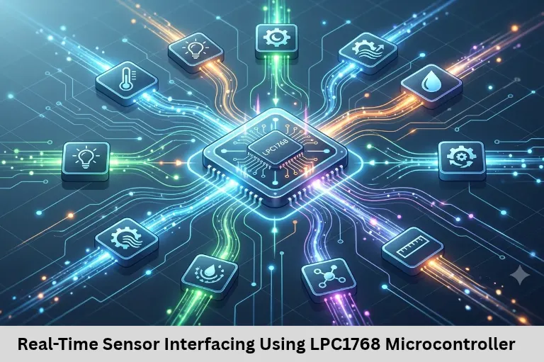
Learn real-time sensor interfacing using LPC1768, ADC programming, UART, I2C, SPI communication, and embedded Internet of Things (IoT) applications with Embedded Tech Development Academy (ETDA).
- Real-Time Sensor Interfacing Using LPC1768 Microcontroller
-
Real-Time Sensor Interfacing Using LPC1768 Microcontroller
- Introduction
- Understanding Real-Time Sensor Interfacing
- ADC Programming for Analog Sensor Interfacing
- Digital Sensor Interfacing Using I2C and SPI
- Real-Time Sensor Data Processing Using Interrupts
- Practical LPC1768 Sensor Projects for Students
- Learn LPC1768 Programming at Embedded Tech Development Academy
-
Frequently Asked Questions
- What is real-time sensor interfacing using LPC1768?
- Does LPC1768 support analog sensor interfacing?
- Which communication protocols are used for LPC1768 sensor interfacing?
- Why are interrupts useful in sensor-based embedded systems?
- Can LPC1768 be used for IoT sensor projects?
- Where can students learn LPC1768 sensor interfacing practically?
- Conclusion
Real-Time Sensor Interfacing Using LPC1768 Microcontroller
Introduction
Real-time sensor interfacing using the LPC1768 microcontroller is an important concept for students learning embedded systems, industrial automation, robotics, and Internet of Things (IoT) applications. Sensors help microcontrollers understand physical conditions such as temperature, pressure, humidity, light intensity, and motion. By connecting sensors with LPC1768, developers can build intelligent systems capable of monitoring environmental conditions and responding immediately to changes.
The LPC1768, based on the ARM Cortex-M3 architecture, offers powerful peripherals, ADC channels, communication interfaces, and interrupt capabilities for developing practical embedded applications. Students searching for a Top Embedded Training Institute in Bangalore can explore Embedded Tech Development Academy (ETDA) to understand these concepts through practical embedded programming, hardware interfacing, and project-based learning.
Understanding Real-Time Sensor Interfacing
Real-time sensor interfacing involves collecting sensor information, processing the received data, and generating an appropriate response within a defined time requirement. It is widely used in automotive electronics, industrial monitoring, medical devices, smart agriculture, and Internet of Things (IoT) systems.
For example, a temperature monitoring system continuously reads sensor values and activates a cooling fan when the temperature exceeds a predefined threshold. The response must occur within an acceptable time to maintain system reliability.
Why Choose LPC1768 for Sensor Interfacing?
The LPC1768 microcontroller provides several hardware features that simplify sensor interfacing and real-time application development.
ARM Cortex-M3 processor operating up to 100 MHz.
12-bit ADC with multiple analog input channels.
Multiple UART interfaces for serial communication.
I2C and SPI interfaces for digital sensor connectivity.
GPIO pins for digital input and output operations.
Timers, PWM modules, and interrupt controllers.
Ethernet connectivity for network-oriented applications.
These features make LPC1768 suitable for developing sensor-based embedded systems that require reliable data acquisition and communication.
Understanding Analog and Digital Sensors
Sensors are generally classified into analog and digital categories depending on their output characteristics.
Analog sensors generate continuous voltage signals corresponding to physical parameters. Examples include analog temperature sensors, potentiometers, and certain pressure sensors. Their outputs require an ADC before the microcontroller can process the information digitally.
Digital sensors provide information through digital communication interfaces or logic-level signals. Sensors using I2C, SPI, and UART can transmit measurement data directly without requiring an external analog-to-digital conversion process.
ADC Programming for Analog Sensor Interfacing
The Analog-to-Digital Converter is one of the most important peripherals available in LPC1768 for sensor applications.
Working Principle of LPC1768 ADC
The LPC1768 ADC converts analog input voltage into a digital value using its 12-bit resolution. With 4096 possible output levels, the ADC can represent input voltage variations with reasonable measurement precision.
For a 3.3 V reference voltage, the approximate ADC resolution is:
ADC Resolution = 3.3 / 4096 = 0.806 mV
The digital output is calculated using:
ADC Value = (Vin / Vref) × 4095
Where Vin represents the input voltage and Vref represents the ADC reference voltage.
Interfacing an Analog Temperature Sensor
An analog temperature sensor such as LM35 can be connected to an LPC1768 ADC input, provided the signal voltage remains within the permitted input range.
The sensor produces an output voltage proportional to temperature. The microcontroller reads the ADC value, converts it into voltage, and calculates the temperature using the sensor’s conversion characteristics.
For an LM35, the approximate output sensitivity is 10 mV per degree Celsius. Therefore, a measured output of 250 mV corresponds to approximately 25°C.
ADC Programming Sequence
A typical ADC application involves the following operations:
Configure the required ADC pin using the appropriate pin function selection registers.
Enable the ADC peripheral through the power control configuration.
Configure the ADC clock and select the required channel.
Start the conversion using the ADC control register.
Monitor the conversion completion flag.
Read the converted result from the ADC data register.
Convert the digital value into meaningful sensor information.
Improving ADC Measurement Accuracy
Students must understand that ADC readings can fluctuate because of electrical noise, unstable sensor outputs, and incorrect grounding.
Using proper circuit grounding, stable power supplies, suitable filtering, and averaging multiple ADC samples improves measurement stability. Signal conditioning may also be required when interfacing sensors with outputs beyond the ADC input range.
Digital Sensor Interfacing Using I2C and SPI
Digital sensor interfacing is widely used in modern embedded systems because it reduces analog signal processing requirements and supports communication with intelligent sensor modules.
I2C Sensor Interfacing
I2C is a two-wire communication protocol consisting of SDA and SCL signals. It allows multiple compatible sensors to communicate with a microcontroller using individual device addresses.
LPC1768 can interface with I2C sensors such as digital temperature sensors, accelerometers, and environmental monitoring modules.
A typical I2C transaction includes a START condition, device address transmission, register selection, data transfer, and STOP condition.
Students should understand acknowledgement handling, address selection, bus timing, and error detection while developing I2C drivers.
SPI Sensor Interfacing
SPI uses separate signals for clock, data transmission, data reception, and chip selection. It generally provides higher communication speeds than I2C and is useful for sensors requiring faster data transfer.
LPC1768 supports SPI-related communication peripherals that can be configured for suitable external devices.
SPI interfacing requires knowledge of clock polarity, clock phase, data order, and chip-select control. These concepts become important when connecting high-speed sensors, displays, and external converters.
Real-Time Sensor Data Processing Using Interrupts
Real-time embedded applications frequently depend on interrupts to respond quickly to sensor events.
Why Interrupts Are Important
Polling continuously checks sensor status, which can consume processor time. Interrupt-driven programming allows the microcontroller to respond when a peripheral or external event requires attention.
For example, an external interrupt can detect a sudden motion event, while an ADC interrupt can indicate that a conversion has completed.
Interrupt Service Routines should remain short and efficient. Lengthy processing inside an interrupt can increase response latency and interfere with other time-critical activities.
Timer-Based Sensor Sampling
Timers help maintain consistent sensor sampling intervals. A temperature monitoring application may collect measurements every 100 milliseconds, while a motion monitoring application may require much faster sampling.
The LPC1768 timer peripherals can generate periodic interrupts for sensor acquisition. This approach improves scheduling predictability and helps students understand real-time task execution.
Practical LPC1768 Sensor Projects for Students
Hands-on projects help students connect theoretical concepts with hardware implementation and debugging.
Temperature Monitoring System
Connect an analog temperature sensor to an ADC channel and display temperature values through UART or an LCD. Add a threshold-based alarm using a buzzer or LED.
Smart Environmental Monitoring
Combine temperature, humidity, and light sensors to monitor environmental conditions. Transmit collected readings to a computer or Internet of Things (IoT) dashboard through an appropriate communication interface.
Industrial Sensor Monitoring
Develop a prototype that monitors sensor measurements and activates outputs when abnormal conditions occur. This project introduces students to industrial automation concepts, event handling, and real-time monitoring.
IoT-Based Sensor Data Transmission
Extend sensor projects by transmitting measurement data through Ethernet or an external wireless communication module. Students can explore data logging, remote monitoring, and basic cloud integration.
Learn LPC1768 Programming at Embedded Tech Development Academy
Embedded Tech Development Academy (ETDA) provides students with opportunities to develop practical knowledge in embedded systems programming and hardware interfacing.
For learners seeking a Top Embedded Training Institute in Bangalore, Embedded Tech Development Academy (ETDA) offers an industry-oriented learning approach that connects microcontroller fundamentals with real-world engineering applications.
Students can strengthen their understanding of Embedded C, ARM microcontrollers, ADC programming, UART, I2C, SPI, RTOS concepts, and Internet of Things (IoT) development through practical exercises.
Learning sensor interfacing helps beginners understand how embedded software interacts with physical hardware. It also prepares learners for projects involving automotive electronics, industrial automation, robotics, and intelligent monitoring systems.
Embedded Tech Development Academy (ETDA)‘s practical training approach and assured placement support help students work toward developing industry-relevant technical skills and preparing for embedded engineering opportunities.
Frequently Asked Questions
What is real-time sensor interfacing using LPC1768?
It is the process of connecting sensors to LPC1768, collecting measurement data, processing information, and responding within specified timing requirements.
Does LPC1768 support analog sensor interfacing?
Yes. LPC1768 includes a 12-bit ADC that converts analog sensor voltage into digital values for processing.
Which communication protocols are used for LPC1768 sensor interfacing?
Common protocols include I2C, SPI, UART, and GPIO-based digital communication, depending on the sensor requirements.
Why are interrupts useful in sensor-based embedded systems?
Interrupts allow the microcontroller to respond efficiently to sensor events and peripheral activities without continuously checking their status.
Can LPC1768 be used for IoT sensor projects?
Yes. LPC1768 supports Ethernet and communication peripherals that can be used with suitable external modules for Internet of Things (IoT) monitoring applications.
Where can students learn LPC1768 sensor interfacing practically?
Students can explore Embedded Tech Development Academy (ETDA), a Top Embedded Training Institute in Bangalore, for embedded systems learning, microcontroller programming, practical projects, and assured placement support.
Conclusion
Real-time sensor interfacing using LPC1768 microcontroller provides a strong foundation for developing intelligent embedded applications. Understanding ADC programming, digital sensor communication, interrupt handling, and timer-based sampling helps students build reliable hardware-oriented solutions.
These skills are valuable for careers involving embedded systems, automotive electronics, industrial automation, robotics, and Internet of Things (IoT) development. Students looking for a Top Embedded Training Institute in Bangalore can consider Embedded Tech Development Academy (ETDA) to strengthen their technical knowledge through practical learning and industry-oriented projects.
ETDA combines embedded programming fundamentals with hardware implementation, project experience, and assured placement support to help aspiring engineers prepare for professional opportunities in the embedded technology industry.
Author: ETDA Trainers
Experience: 10+ Years of Industry Experience in Embedded Systems, IoT, and Embedded C Programming