
Smart Home Automation Using ESP32 and IoT Guide
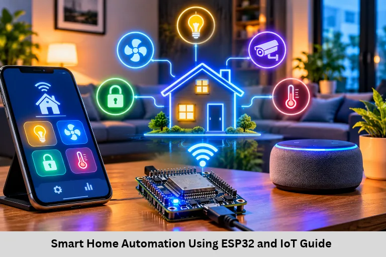
Learn smart home automation using ESP32 and Internet of Things (IoT), including sensors, relay control, Wi-Fi communication, system architecture, and practical project development. Embedded Tech Development Academy (ETDA).
- Smart Home Automation Using ESP32 and IoT Guide
-
Smart Home Automation Using ESP32 and IoT
- Introduction to Smart Home Automation
- System Architecture of an ESP32 Smart Home
- Connecting Sensors and Relay Outputs
- ESP32 Firmware for Motion-Based Light Control
- IoT Dashboard and Remote Control
- Testing, Debugging, and Security
- Building Embedded Systems Skills Through an ETDA Project
- Frequently Asked Questions
- Conclusion
Smart Home Automation Using ESP32 and IoT
Introduction to Smart Home Automation
Smart home automation allows users to monitor and control lights, fans, appliances, and environmental conditions through smartphones or web dashboards. By combining an ESP32 microcontroller with Internet of Things (IoT) connectivity, students can build affordable automation systems that demonstrate real embedded systems skills. For learners exploring this field, the Top Embedded Training Institute in Bangalore can provide practical exposure to microcontrollers, communication protocols, and project development.
The ESP32 is popular for Internet of Things (IoT) projects because it integrates Wi-Fi and Bluetooth, offers multiple GPIO pins, and supports interfaces such as I2C, SPI, and UART. This makes it suitable for connecting sensors, controlling outputs, and exchanging data with cloud platforms. A smart home project is also an excellent way to understand how firmware, hardware, networking, and application software work together.
What Is Smart Home Automation?
Smart home automation uses electronic devices, sensors, controllers, and communication networks to automate household functions. A system may switch lights based on motion, monitor room temperature, detect door opening, or allow remote appliance control.
In an Internet of Things (IoT)-based design, devices collect information and communicate it to a local network or cloud service. Users can view status and send commands through a mobile application or browser. Automation rules can also run locally, so selected functions continue even when internet access is unavailable.
Why Use ESP32 for Home Automation?
The ESP32 offers a strong combination of processing capability, connectivity, and cost. Its integrated Wi-Fi reduces the need for an external networking module, while GPIO pins allow direct interfacing with digital sensors and driver circuits.
These capabilities make ESP32 a practical platform for learning embedded systems and developing scalable Internet of Things (IoT) prototypes.
System Architecture of an ESP32 Smart Home
A typical smart home architecture contains four major layers: sensing, processing, communication, and user interface. Sensors measure physical conditions, the ESP32 executes firmware logic, Wi-Fi transfers information, and a dashboard displays data or sends commands.
Hardware Components Required
ESP32 development board: Main controller that runs the application firmware.
PIR sensor: Detects movement for occupancy-based lighting.
Temperature and humidity sensor: Measures indoor environmental conditions.
Relay module: Switches suitable electrical loads using a control signal.
LED or low-voltage lamp: Demonstrates output control safely.
Communication Flow in Smart Home Automation
When a PIR sensor detects movement, its output changes state and the ESP32 reads the signal through a GPIO input. The firmware checks the condition, activates the output driver, and optionally publishes the event to an Internet of Things (IoT) dashboard.
A user can also send a command from a dashboard to turn an appliance on or off. The ESP32 receives the command over Wi-Fi, validates it, updates the output, and reports the new state.
Sensor-to-Controller Communication
Sensors provide digital or analog information to the microcontroller. The ESP32 reads these values through GPIO, ADC, I2C, or other supported interfaces, depending on the sensor type.
Controller-to-Dashboard Communication
After processing sensor information, the ESP32 can transmit readings and device status through Wi-Fi. The dashboard displays the information and allows users to send control commands.
Example of a Motion Detection Event
When a PIR sensor detects movement, the ESP32 receives a HIGH signal. The controller activates a light output and publishes a motion notification to the dashboard. This simple event demonstrates how sensing, processing, and communication combine in an Internet of Things (IoT) application.
Connecting Sensors and Relay Outputs
PIR Sensor Interfacing with ESP32
A PIR sensor commonly provides a digital output that becomes HIGH when motion is detected. Connect its output to a suitable ESP32 GPIO input and configure the pin as an input in firmware.
The controller continuously monitors the sensor and decides whether the light should remain ON or OFF. This application introduces GPIO configuration, digital input reading, conditional logic, and output control.
Relay Module and Appliance Control
A relay allows a low-voltage controller to operate a separate electrical circuit. The ESP32 GPIO should control a properly designed relay module or transistor driver; it must not directly drive a relay coil or mains load.
For student prototypes, use an LED or low-voltage DC load first. Mains electricity presents serious shock and fire risks, so real household wiring must be installed inside suitable enclosures by a qualified electrician. Isolation, fuse protection, load ratings, and safe clearances are essential.
Relay Driver Operation
The relay driver receives a control signal from the ESP32 and switches the relay coil through an appropriate transistor or driver circuit. This protects the microcontroller from excessive current and inductive voltage spikes.
Important Hardware Safety Considerations
Use a correctly rated relay module, suitable power supply, isolation, and protective components. Never connect household AC directly to ESP32 pins or an unsecured breadboard.
ESP32 Firmware for Motion-Based Light Control
The following Arduino-style example demonstrates basic motion-controlled output. It assumes a suitable low-voltage LED or driver input is connected to the selected output pin.
const int pirPin = 27;
const int lightPin = 26;

void setup() {
  pinMode(pirPin, INPUT);
  pinMode(lightPin, OUTPUT);
  digitalWrite(lightPin, LOW);
  Serial.begin(115200);
}

void loop() {
  int motion = digitalRead(pirPin);

  if (motion == HIGH) {
    digitalWrite(lightPin, HIGH);
    Serial.println("Motion detected: Light ON");
  } else {
    digitalWrite(lightPin, LOW);
    Serial.println("No motion: Light OFF");
  }

  delay(100);
}
Understanding the Firmware
The program configures the PIR pin as an input and the light pin as an output. The loop function reads the sensor continuously and changes the output depending on the detected motion state.
A more complete design should use a non-blocking timer instead of relying on repeated delays, especially when multiple sensors or network tasks must run together.
Adding Wi-Fi Connectivity
To connect the ESP32 to a router, firmware uses the Wi-Fi library and network credentials. After connection, the controller can communicate with a local web server, MQTT broker, or supported Internet of Things (IoT) dashboard.
Managing Wi-Fi Connection Failures
The firmware should detect disconnection and attempt reconnection without blocking sensor monitoring. Connection status indicators and serial debugging messages help students identify network problems during development.
IoT Dashboard and Remote Control
A dashboard provides a user-friendly interface for monitoring sensor values and controlling outputs. Depending on the chosen platform, ESP32 data may be transmitted through HTTP requests, MQTT messages, or a platform-specific library.
MQTT-Based Communication
MQTT is a lightweight publish-subscribe protocol commonly used in Internet of Things (IoT). The ESP32 can publish room temperature to a topic such as home/room1/temperature and subscribe to home/room1/light/set.
A broker routes messages between publishers and subscribers. This separates device firmware from the user interface and makes it easier to add more nodes. MQTT topics, retained messages, quality-of-service levels, and reconnect handling are useful concepts for students to practice.
Local Automation Versus Cloud Automation
Local automation executes rules on the ESP32 or within the home network. It can respond quickly and continue operating without internet access. Cloud automation enables remote monitoring, historical data storage, and access from outside the home, but depends on connectivity and platform availability.
Example Smart Home Automation Rules
Switch a light ON when motion is detected during evening hours.
Send a notification when a door sensor changes state.
Turn on ventilation when room temperature exceeds a threshold.
Display energy or environmental readings on a dashboard.
Allow manual override even when automatic mode is enabled.
Testing, Debugging, and Security
A smart home prototype should be tested one module at a time. Verify sensor readings through Serial Monitor, check GPIO behavior with an LED, confirm Wi-Fi connectivity, and then test dashboard commands. This step-by-step approach helps identify whether a fault comes from wiring, firmware, networking, or application logic.
Security is equally important. Use strong Wi-Fi credentials, authenticated dashboard access, encrypted communication where supported, and regular firmware updates. Avoid hard-coded public credentials and unnecessary open ports. Device logs should not reveal passwords or private household information.
Common Problems During Development
Students may encounter incorrect sensor readings, unstable Wi-Fi connections, relay switching problems, or dashboard communication failures. These issues can be diagnosed by checking supply voltage, GPIO configuration, wiring, network settings, and firmware execution.
Debugging Using Serial Monitor
Serial Monitor helps developers observe sensor values, connection status, and program execution. Adding meaningful debugging messages makes it easier to identify where the automation logic is failing.
Improving Project Reliability
Use watchdog mechanisms where appropriate, handle communication timeouts, validate incoming commands, and design firmware so that network failures do not disable essential local automation.
Building Embedded Systems Skills Through an ETDA Project
At Embedded Tech Development Academy (ETDA), students can connect classroom concepts with practical embedded systems projects. A smart home automation project offers experience in ESP32 programming, GPIO configuration, sensor interfacing, Wi-Fi communication, debugging, and Internet of Things (IoT) integration.
Learners can extend the basic prototype with multiple rooms, energy monitoring, MQTT messaging, mobile dashboards, and real-time alerts. Such project work helps students understand the complete development cycle—from selecting hardware and writing firmware to testing, troubleshooting, and documenting results.
Skills Students Can Develop
Students can practice embedded C programming, microcontroller peripherals, communication protocols, and firmware debugging. These concepts are useful in Internet of Things (IoT) development, industrial automation, automotive electronics, and other embedded applications.
Industry-Oriented Project Learning
Choosing the Top Embedded Training Institute in Bangalore can be valuable for students seeking structured hands-on learning, industry-oriented practice, and assured placement support as they prepare for technical roles.
Extending the Project for Advanced Learning
Students exploring the Top Embedded Training Institute in Bangalore should look for opportunities to build and demonstrate complete hardware-based projects instead of learning concepts only through theory. Practical experience with embedded systems and Internet of Things (IoT) can strengthen technical understanding and project confidence.
Frequently Asked Questions
What is ESP32 smart home automation?
It is a system that uses an ESP32 controller, sensors, and Wi-Fi to monitor or control household devices through firmware, dashboards, or automation rules.
Can ESP32 control home appliances?
Yes. ESP32 can operate suitable driver or relay modules, but GPIO pins must never be connected directly to mains appliances. Use safe isolation and qualified electrical installation.
Which sensors are useful for smart home projects?
PIR sensors, temperature and humidity sensors, door magnetic sensors, light sensors, and smoke or gas sensors are common choices, depending on the project requirements.
Is internet access always required?
No. Local automation can run within the home network or directly on the ESP32. Internet access is mainly needed for cloud services and remote access.
Why is MQTT used in IoT home automation?
MQTT provides lightweight publish-subscribe messaging, allowing devices and dashboards to exchange data efficiently through a broker.
How can students learn smart home automation professionally?
Students can practice ESP32 coding, sensor interfacing, networking, debugging, and project documentation through hands-on embedded systems training at Embedded Tech Development Academy (ETDA), along with assured placement support.
Conclusion
Smart home automation using ESP32 and Internet of Things (IoT) is a practical project for understanding how microcontrollers, sensors, firmware, and wireless communication work together. Starting with motion-based lighting and gradually adding MQTT, dashboards, security, and local automation builds strong technical confidence.
For students interested in embedded systems, Embedded Tech Development Academy (ETDA) can help translate these concepts into hands-on project experience. The Top Embedded Training Institute in Bangalore should emphasize practical implementation, debugging, and real hardware exposure—not only theory. With guided learning and assured placement support, students can strengthen the skills needed to explore embedded systems and Internet of Things (IoT) development opportunities.
Author: ETDA Trainers
Experience: 10+ Years of Industry Experience in Embedded Systems, IoT, and Embedded C Programming