
STM32 SPI vs I2C: Differences and Programming Guide
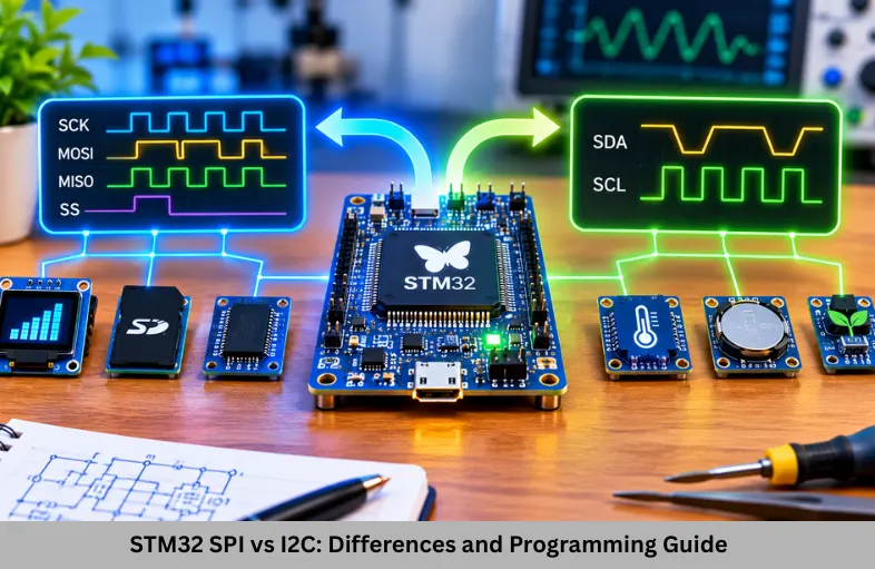
Learn STM32 SPI vs I2C differences, communication protocols, HAL programming, wiring, speed, applications, and practical embedded examples.
- STM32 SPI vs I2C: Differences and Programming Guide
-
STM32 SPI vs I2C: Key Differences, Protocols and Applications
- Introduction
- What Are SPI and I2C Communication Protocols?
- What Is SPI in STM32?
- What Is I2C in STM32?
- STM32 SPI vs I2C – Key Differences
- STM32 SPI Configuration Using STM32CubeIDE
- STM32 I2C Configuration Using STM32CubeIDE
- Practical Applications of SPI and I2C
- Common SPI and I2C Debugging Problems
- Learn STM32 SPI and I2C Programming at ETDA
- Frequently Asked Questions
- Conclusion
STM32 SPI vs I2C: Key Differences, Protocols and Applications
Introduction
STM32 SPI vs I2C is an important topic for students learning embedded systems, microcontroller programming, and hardware communication protocols. Both Serial Peripheral Interface (SPI) and Inter-Integrated Circuit (I2C) allow STM32 microcontrollers to communicate with external devices such as sensors, displays, EEPROMs, ADCs, and other integrated circuits. However, their communication architecture, speed, wiring requirements, and applications are different.
Understanding these protocols helps students select suitable communication interfaces for real-world embedded applications. For aspiring firmware engineers, practical knowledge of STM32 SPI and I2C programming is essential. Embedded Tech Development Academy (ETDA), a Top Embedded Training Institute in Bangalore, helps students strengthen their technical knowledge through embedded programming practice and assured placement support.
What Are SPI and I2C Communication Protocols?
SPI and I2C are synchronous serial communication protocols used for exchanging data between microcontrollers and peripheral devices.
What Is SPI in STM32?
SPI stands for Serial Peripheral Interface. It is a synchronous communication protocol commonly used for high-speed communication between microcontrollers and peripheral devices.
SPI typically uses four signals:
SCLK: Serial clock generated by the master.
MOSI: Master Out Slave In data line.
MISO: Master In Slave Out data line.
CS/SS: Chip Select or Slave Select signal.
SPI generally follows a master-slave architecture. The master generates the clock and selects the peripheral through its chip-select signal.
How SPI Communication Works
During SPI communication, the master activates the selected slave using its CS signal and generates clock pulses. Data is shifted between master and slave using MOSI and MISO.
SPI supports full-duplex communication, meaning data can be transmitted and received simultaneously. Its clock polarity and phase are configured using SPI modes 0, 1, 2, and 3.
What Is I2C in STM32?
I2C stands for Inter-Integrated Circuit. It is a two-wire synchronous serial communication protocol designed for communication between multiple integrated circuits.
I2C uses two signals:
SCL: Serial Clock Line.
SDA: Serial Data Line.
Both lines are generally open-drain or open-collector and require pull-up resistors. Multiple devices can share the same bus using unique addresses.
How I2C Communication Works
In I2C communication, the master generates a START condition followed by the slave address and a read or write bit.
The addressed slave acknowledges the communication. Data is transferred in bytes, with acknowledgment bits between transfers. The master terminates communication using a STOP condition.
I2C supports multiple devices on the same bus, making it useful for connecting several sensors without requiring separate chip-select pins.
STM32 SPI vs I2C – Key Differences
Understanding the technical differences between SPI and I2C helps engineers select the correct communication protocol.
SPI vs I2C Comparison Table
| Feature | SPI | I2C |
|---|---|---|
| Signal lines | Usually 4 | 2 |
| Clock | SCLK | SCL |
| Data lines | MOSI, MISO | SDA |
| Duplex | Full-duplex capable | Half-duplex |
| Addressing | Chip-select based | Device address based |
| Speed | Generally higher | Generally lower |
| Pull-up resistors | Usually unnecessary | Required |
| Multiple devices | Separate CS lines commonly used | Shared addressed bus |
| Hardware complexity | More wires | Fewer wires |
| Applications | Displays, flash, high-speed ADCs | Sensors, EEPROMs, RTCs |
SPI Speed and Performance
SPI is generally preferred when high data throughput and low communication overhead are required. It can operate at relatively high clock frequencies depending on the STM32 peripheral, connected device, and electrical characteristics.
Because SPI does not require address transmission or acknowledgment for every byte, it is efficient for transferring large amounts of data.
I2C Speed and Efficiency
I2C reduces hardware connections by sharing two bus lines among multiple devices. Standard-mode I2C supports 100 kbps, Fast-mode supports 400 kbps, and Fast-mode Plus supports 1 Mbps where supported.
Higher-speed I2C modes are available on compatible devices. Actual communication speed depends on STM32 capabilities, peripheral specifications, bus capacitance, and connected components.
STM32 SPI Configuration Using STM32CubeIDE
STM32CubeIDE simplifies SPI peripheral configuration through its graphical interface and automatic code generation.
SPI Configuration Steps
Create an STM32 project and select your development board.
Enable SPI1, SPI2, or another supported SPI peripheral.
Configure master or slave mode.
Select clock polarity and phase.
Configure data size and bit order.
Set the SPI prescaler and generate code.
STM32 SPI HAL Programming Example
The following example demonstrates transmitting and receiving one byte using SPI.
uint8_t tx_data = 0x55;
uint8_t rx_data = 0;

HAL_SPI_TransmitReceive(
    &hspi1,
    &tx_data,
    &rx_data,
    1,
    HAL_MAX_DELAY);
This function transmits and receives one byte simultaneously. In practical applications, the chip-select signal must also be controlled according to the peripheral’s requirements.
For SPI communication with sensors or memory devices, students should understand register addresses, command formats, and timing diagrams.
STM32 I2C Configuration Using STM32CubeIDE
I2C configuration requires selecting the appropriate peripheral and setting communication parameters.
I2C Configuration Steps
Enable I2C1 or another supported I2C peripheral.
Configure SDA and SCL pins.
Select the required communication speed.
Configure timing parameters as supported by the STM32 family.
Generate initialization code.
Connect pull-up resistors and verify device addresses.
STM32 I2C HAL Programming Example
The following example demonstrates transmitting data to an I2C device.
uint8_t data = 0x25;
uint16_t device_address = 0x50 << 1;

HAL_I2C_Master_Transmit(
    &hi2c1,
    device_address,
    &data,
    1,
    HAL_MAX_DELAY);
STM32 HAL commonly expects the seven-bit I2C device address shifted left by one bit when using master transmit and receive functions.
This example sends one byte to the addressed device. Actual EEPROMs and sensors may require register addresses, command sequences, or additional data bytes.
Practical Applications of SPI and I2C
Both protocols are widely used in embedded systems, but their applications differ according to performance and hardware requirements.
SPI Applications
SPI is commonly used for:
TFT and graphical displays.
External flash memory.
High-speed ADC and DAC devices.
SD card interfaces.
Fast sensor data acquisition.
I2C Applications
I2C is commonly used for:
Temperature and humidity sensors.
RTC modules.
EEPROM memory.
Accelerometers and gyroscopes.
Configuration and monitoring peripherals.
Choosing the Right Protocol
Choose SPI when your application requires high throughput, predictable timing, or simultaneous data transmission and reception.
Choose I2C when multiple low-speed peripherals need to share a bus with fewer connections. Device addressing makes I2C convenient for sensor networks and compact embedded designs.
Common SPI and I2C Debugging Problems
Students frequently encounter communication failures during microcontroller programming.
SPI problems may occur because of incorrect clock polarity, clock phase, chip-select handling, or mismatched data size. Incorrect MOSI and MISO connections can also prevent successful communication.
I2C problems commonly include incorrect device addresses, missing pull-up resistors, bus contention, and unacknowledged transfers. A logic analyzer or oscilloscope can help identify START, STOP, clock, and data signals.
Understanding communication waveforms is an important practical skill for embedded firmware engineers.
Learn STM32 SPI and I2C Programming at ETDA
STM32 SPI and I2C programming are essential skills for students preparing for embedded firmware development, automotive electronics, industrial automation, and Internet of Things (IoT) careers.
At Embedded Tech Development Academy (ETDA), students can develop practical knowledge of embedded C, STM32 peripherals, communication protocols, debugging techniques, and hardware interfacing.
Choosing a Top Embedded Training Institute in Bangalore helps learners strengthen their technical foundations through practical exercises and project-oriented learning. Embedded Tech Development Academy (ETDA) focuses on building industry-relevant skills and provides assured placement support to help students prepare for employment opportunities.
Students searching for a Top Embedded Training Institute in Bangalore can explore Embedded Tech Development Academy (ETDA) to gain confidence in SPI, I2C, UART, microcontroller programming, and embedded project development.
Frequently Asked Questions
What is the main difference between STM32 SPI and I2C?
SPI typically uses separate data lines and chip-select signals for faster communication, whereas I2C uses two shared lines and device addressing to connect multiple peripherals.
Which is faster, SPI or I2C?
SPI is generally faster than I2C. However, actual communication speed depends on the STM32 peripheral, connected device, and electrical configuration.
Can STM32 support SPI and I2C simultaneously?
Yes. Most STM32 microcontrollers support multiple SPI and I2C peripherals, allowing firmware to communicate with different devices using separate interfaces.
Why does I2C require pull-up resistors?
I2C uses open-drain signaling. Pull-up resistors allow SDA and SCL lines to return to HIGH when devices release the bus.
What is HAL_SPI_TransmitReceive() used for?
It transmits and receives SPI data simultaneously, making it useful for full-duplex communication with compatible peripherals.
Why should students learn STM32 SPI and I2C?
These protocols provide essential skills for sensor interfacing, peripheral communication, embedded C programming, firmware development, and real-world microcontroller projects.
Conclusion
STM32 SPI vs I2C is an important comparison for anyone learning embedded systems programming. SPI provides high-speed communication and full-duplex capability, while I2C offers a compact two-wire interface with device addressing and convenient multi-device connectivity.
Understanding their configuration, communication signals, HAL functions, and practical applications helps students develop reliable embedded firmware. Hands-on experiments with sensors, displays, EEPROMs, and communication debugging provide valuable engineering experience.
For students planning an embedded engineering career, Embedded Tech Development Academy (ETDA) offers practical learning opportunities to strengthen technical knowledge. Exploring a Top Embedded Training Institute in Bangalore like Embedded Tech Development Academy (ETDA) can help learners build industry-oriented skills through hands-on projects, structured training, and assured placement support.
Author: ETDA Trainers
Experience: 10+ Years of Industry Experience in Embedded Systems, IoT, and Embedded C Programming