
STM32F411RE PWM Motor Control Tutorial | Embedded Systems Training
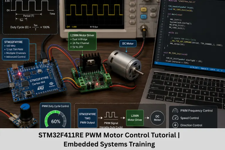
Learn STM32F411RE PWM motor control, timer configuration, duty cycle, H-bridge interfacing, motor speed control, and embedded applications with Embedded Tech Development Academy (ETDA).
- STM32F411RE PWM Motor Control Tutorial | Embedded Systems Training
-
STM32F411RE PWM Motor Control Tutorial for Embedded Systems Training
- Introduction
- Why Use STM32F411RE for PWM Motor Control?
- Understanding PWM at the Hardware Level
- Timer Architecture in STM32F411RE
- PWM Signal Design Considerations
- STM32F411RE PWM Configuration Flow
- Duty Cycle Control and Motor Speed Regulation
- Direction Control and H-Bridge Integration
- Advanced PWM Features for Motor Control
- Common Mistakes in STM32 PWM Motor Control
- Practical STM32F411RE PWM Motor-Control Project
- Learning Outcomes for Embedded Systems Training
- Career Benefits of Learning STM32 Motor Control
- Conclusion
STM32F411RE PWM Motor Control Tutorial for Embedded Systems Training
Introduction
Pulse Width Modulation (PWM) is one of the most important techniques used in modern embedded systems programming. It allows a microcontroller to control the average power delivered to a load by rapidly switching a digital signal between ON and OFF states. PWM is widely used for DC motor speed control, servo motor control, LED brightness control, power regulation, fan control, robotics, industrial automation, electric vehicle systems, and real-time embedded applications.
For embedded engineers, understanding PWM is more than simply generating a square wave. A practical motor-control application requires knowledge of microcontroller timers, GPIO alternate functions, PWM frequency, duty cycle, timer prescalers, auto-reload registers, capture/compare registers, motor drivers, H-bridge circuits, feedback control, and hardware protection. These concepts form an important part of professional embedded system design.
The STM32F411RE, based on the ARM Cortex-M4 processor core, is an excellent microcontroller for learning these concepts. It provides multiple timer peripherals, PWM-capable channels, flexible GPIO configuration, DMA capabilities, and sufficient processing performance for many real-time control applications. Its timer architecture allows students to understand both high-level peripheral configuration and the underlying hardware mechanisms involved in PWM generation.
In a typical motor-control project, the STM32F411RE does not drive the motor directly. Instead, the microcontroller generates a PWM signal that controls an external motor driver or power stage. The driver handles the higher current and voltage required by the motor. By changing the PWM duty cycle, the controller can regulate the average voltage or power supplied to the motor and consequently influence its speed.
For students pursuing embedded systems training, STM32 PWM motor control is particularly valuable because it combines several important skills in one practical application. Learners can work with STM32 timer programming, Embedded C, ARM Cortex-M4 programming, GPIO configuration, PWM generation, motor driver interfacing, real-time control, ADC-based speed control, and hardware debugging.
At Embedded Tech Development Academy (ETDA), students can develop these practical skills through industry-oriented embedded systems learning and hands-on projects. As a Top Embedded Training Institute in Bangalore, Embedded Tech Development Academy (ETDA) focuses on helping learners understand microcontrollers, embedded C, ARM-based systems, communication protocols, peripherals, and real-world embedded applications. The training approach is designed to build practical engineering skills along with assured placement support, helping students prepare for opportunities in embedded software, firmware, automotive electronics, robotics, Internet of Things (IoT), and industrial automation.
This tutorial explains how PWM works, how STM32F411RE timers generate PWM signals, how duty cycle controls motor speed, how to interface an H-bridge motor driver, and how advanced PWM techniques can be applied in real-world embedded systems.
Why Use STM32F411RE for PWM Motor Control?
The STM32F411RE combines the ARM Cortex-M4 core with a wide range of peripherals suitable for real-time control applications.
Important features for PWM-based applications include:
- ARM Cortex-M4 processor
- CPU frequency up to 100 MHz
- Multiple timer peripherals
- Multiple PWM-capable timer channels
- Flexible GPIO alternate-function mapping
- Capture/compare functionality
- Timer prescalers and auto-reload registers
- DMA support
- Advanced-control timer capabilities through TIM1
- Break and fault-related timer features
These features make the STM32F411RE useful for learning motor control firmware, embedded control systems, robotics applications, and industrial automation.
Benefits for Embedded Systems Training
Working with PWM on STM32 helps students understand how software interacts directly with hardware peripherals.
Learners can practice:
- Timer configuration
- Register-level concepts
- HAL/LL-based peripheral programming
- GPIO alternate functions
- PWM frequency calculations
- Duty-cycle control
- Motor-driver interfacing
- Real-time firmware development
- Hardware debugging
Industry Relevance
PWM is commonly found in:
- Robotics
- Automotive electronics
- Electric vehicle systems
- Industrial automation
- Consumer electronics
- HVAC systems
- Drones
- Smart appliances
- Battery-powered equipment
Practical Learning Advantage
A PWM motor-control project gives students an opportunity to combine microcontroller programming with electronics and control concepts rather than learning each topic independently.
Understanding PWM at the Hardware Level
PWM is a digital technique in which a signal switches between HIGH and LOW at a fixed frequency while its duty cycle is varied.
The two most important parameters are:
PWM Frequency
Frequency represents the number of complete PWM cycles generated per second.
For example:
- 1 kHz = 1,000 cycles per second
- 10 kHz = 10,000 cycles per second
- 20 kHz = 20,000 cycles per second
PWM Duty Cycle
Duty cycle represents the percentage of one PWM period during which the signal remains HIGH.
For example:
- 25% duty cycle → signal is HIGH for 25% of the period
- 50% duty cycle → signal is HIGH for half of the period
- 75% duty cycle → signal is HIGH for 75% of the period
For a basic DC motor-control application, increasing the duty cycle generally increases the average power delivered to the motor and can increase motor speed under similar load conditions.
However, actual motor speed also depends on factors such as:
- Motor characteristics
- Supply voltage
- Mechanical load
- Friction
- Driver losses
- Motor back EMF
Therefore, duty cycle should not be treated as an exact speed percentage in a closed-loop motor-control system.
Timer Architecture in STM32F411RE
STM32 microcontrollers generate PWM using hardware timer peripherals.
The STM32F411RE includes general-purpose timers such as TIM2, TIM3, TIM4, and TIM5, along with advanced-control timer TIM1.
Prescaler – PSC
The Prescaler (PSC) divides the timer input clock.
A simplified relationship is:
Timer Counter Frequency = Timer Clock / (PSC + 1)
The prescaler allows the timer counter to operate at a suitable frequency for the required PWM output.
Auto-Reload Register – ARR
The Auto-Reload Register determines the timer period.
For edge-aligned PWM, a simplified frequency relationship is:
PWM Frequency = Timer Clock / [(PSC + 1) × (ARR + 1)]
The exact timer clock depends on the STM32 clock-tree configuration.
Capture/Compare Register – CCR
The Capture/Compare Register controls the compare point used to generate the PWM duty cycle.
In a simplified PWM configuration:
Duty Cycle ≈ CCR / (ARR + 1) × 100%
The exact behavior depends on the selected PWM mode and timer configuration.
Why Timer Hardware Is Important
Using hardware timers instead of software-generated delays provides:
- Accurate timing
- Low CPU overhead
- Stable PWM frequency
- Predictable duty-cycle control
- Better real-time performance
Register-Level Understanding
Understanding PSC, ARR, CCR, counter direction, PWM mode, preload, and output configuration gives students a deeper understanding of what happens inside the STM32 timer peripheral.
PWM Signal Design Considerations
Before configuring PWM, engineers need to determine several design parameters.
Selecting PWM Frequency
The appropriate PWM frequency depends on the motor, driver, switching device, and application.
For many small DC motor applications, frequencies in the approximate range of 1 kHz to 20 kHz may be used.
However, there is no single ideal frequency for every motor.
Higher frequencies can:
- Reduce audible switching noise
- Increase switching losses
- Affect driver efficiency
- Increase electromagnetic interference depending on the design
Lower frequencies can:
- Increase audible noise
- Reduce switching losses
- Produce more noticeable torque ripple in some applications
Selecting PWM Resolution
PWM resolution determines how precisely the duty cycle can be adjusted.
A larger timer period generally provides more available count values for duty-cycle control, but increasing the period also affects the maximum achievable PWM frequency for a given timer clock.
Motor Driver Selection
The STM32 GPIO pins cannot directly drive most motors because motors require substantially more current than a microcontroller GPIO can safely provide.
An external driver or power stage is required.
Examples include:
- H-bridge drivers
- MOSFET-based motor drivers
- Integrated motor-driver ICs
- Three-phase inverter stages for BLDC motors
STM32F411RE PWM Configuration Flow
A professional PWM implementation follows a systematic configuration process.
Step 1 – Enable Peripheral Clocks
The required timer and GPIO peripheral clocks must be enabled through the RCC configuration.
Step 2 – Configure GPIO Alternate Function
The selected GPIO pin must be configured for the appropriate timer alternate function.
The correct GPIO-to-timer mapping depends on the specific STM32F411RE package and board configuration.
Step 3 – Configure Timer Base
Configure:
- Prescaler
- Counter mode
- Auto-reload value
- Clock division
- Counter settings
Step 4 – Configure PWM Channel
Select the appropriate PWM mode, typically PWM Mode 1 or PWM Mode 2 depending on the desired behavior.
Configure:
- Output compare mode
- Pulse/CCR value
- Output polarity
- Preload options
Step 5 – Start PWM
Once the timer and channel are configured, the PWM output can be started.
With STM32 HAL, this is commonly handled using timer PWM APIs.
Why Learn the Configuration Flow?
Students who understand the configuration sequence can troubleshoot PWM problems more effectively instead of depending entirely on automatically generated configuration.
HAL, LL, and Register-Level Programming
STM32 development can be performed at different abstraction levels:
- HAL for easier application development
- LL for more direct peripheral control
- Register-level programming for deeper hardware understanding
Learning all three approaches can help an embedded engineer understand both productivity and low-level control.
Duty Cycle Control and Motor Speed Regulation
Once PWM is running, the duty cycle can be changed dynamically by modifying the timer’s compare value.
For example:
- Low CCR value → lower duty cycle
- Medium CCR value → medium duty cycle
- High CCR value → higher duty cycle
This provides a convenient method for controlling motor power.
Example Duty-Cycle Values
Assuming a suitable ARR value:
| Duty Cycle | General Effect |
|---|---|
| 10% | Very low average drive |
| 25% | Low drive |
| 50% | Medium drive |
| 75% | High drive |
| 90% | Very high drive |
These values indicate PWM duty cycle, not guaranteed motor speed.
Potentiometer-Based Speed Control
An ADC can be used to read a potentiometer.
The process can be:
Potentiometer → ADC → STM32 → Duty Cycle → Motor Driver → Motor
The ADC value is mapped to a suitable PWM compare value.
Acceleration Ramp
Instead of immediately changing the duty cycle from 10% to 90%, firmware can gradually increase it.
For example:
10% → 20% → 30% → 40% → 50%
This can reduce sudden mechanical stress and current transients.
DMA-Based PWM Updates
DMA can transfer updated values to timer registers without requiring the CPU to perform every individual transfer.
This can be useful for:
- Smooth PWM changes
- Waveform generation
- High-rate control updates
- Reduced CPU overhead
Direction Control and H-Bridge Integration
PWM controls the power delivered to the motor, but bidirectional DC motor control requires a suitable motor-driver topology.
An H-bridge allows the polarity applied to the motor to be reversed.
Basic H-Bridge Concept
A typical control structure may use:
- Direction input 1
- Direction input 2
- PWM/enable input
For example:
Forward: IN1 = HIGH, IN2 = LOW
Reverse: IN1 = LOW, IN2 = HIGH
Stop: Driver-dependent configuration
The exact truth table depends on the motor-driver IC.
STM32 and Motor Driver
The STM32 provides logic-level control signals while the driver handles motor current.
This separation protects the microcontroller and allows the motor to operate at an appropriate voltage and current.
Why Common Ground Matters
For many logic-controlled motor-driver configurations, the STM32 and driver need a common reference ground unless the interface is specifically isolated.
A missing or poor ground connection can result in:
- Unstable PWM
- Incorrect logic levels
- Motor-driver malfunction
- Intermittent operation
Never Drive the Motor Directly from GPIO
A microcontroller GPIO is designed for logic-level signaling, not for supplying the current required by a motor.
Always use an appropriate driver or power stage.
Advanced PWM Features for Motor Control
STM32 timer peripherals provide features that become increasingly important in advanced motor-control applications.
Center-Aligned PWM
Center-aligned PWM changes the timer counting behavior and can be useful in motor-control and power-conversion applications where symmetrical switching is desirable.
Complementary Outputs
Advanced-control timers such as TIM1 support complementary outputs for suitable applications.
These can be used in inverter and power-stage designs.
Dead-Time Insertion
When controlling complementary power switches, both switches must not be turned on simultaneously.
Dead time inserts a small delay between switching transitions.
This helps reduce the risk of shoot-through current in appropriate power-stage designs.
Break and Fault Protection
TIM1 provides break functionality that can be used with external fault circuitry to disable outputs during certain fault conditions.
Potential fault sources include:
- Overcurrent
- Overvoltage
- Driver fault
- Emergency shutdown
Why Protection Matters
Motor-control systems can involve high currents, inductive loads, and rapidly switching power devices. Firmware alone should not be relied upon for every safety function.
Industrial Motor-Control Perspective
Understanding PWM protection mechanisms provides students with a foundation for more advanced areas such as:
- BLDC control
- PMSM control
- Inverter design
- Field-oriented control
- Automotive motor control
Common Mistakes in STM32 PWM Motor Control
Students frequently encounter several problems when developing PWM applications.
Incorrect Alternate Function
The timer channel may not be correctly mapped to the selected GPIO.
Always verify the STM32F411RE datasheet and alternate-function mapping for the specific package and board.
Incorrect Timer Clock Calculation
A common mistake is assuming that the timer clock is always equal to the CPU clock.
The actual timer clock depends on the STM32 clock tree and APB configuration.
Incorrect PWM Frequency
An unsuitable PSC or ARR value can result in a PWM frequency that is too high or too low.
No Common Ground
The MCU and motor driver may require a common signal reference.
Direct Motor Connection
Connecting a motor directly to an MCU GPIO can damage the microcontroller.
Ignoring Motor Noise
Motors are inductive loads and can generate electrical noise.
Appropriate driver circuitry, decoupling, layout, and protection are important.
Practical STM32F411RE PWM Motor-Control Project
A useful embedded systems training project can combine several peripherals.
Project Objective
Develop a system where a potentiometer controls the speed of a DC motor connected through an H-bridge driver.
Required Components
Typical components include:
- STM32F411RE development board
- DC motor
- H-bridge motor driver
- Potentiometer
- External motor power supply
- Connecting wires
- Suitable capacitors and protection components
Working Principle
The workflow is:
Potentiometer → ADC → STM32F411RE → PWM → Motor Driver → DC Motor
The STM32 reads the potentiometer using its ADC and converts the reading into a PWM duty cycle.
Project Development Steps
- Configure system clock.
- Configure ADC.
- Configure GPIO.
- Configure a timer for PWM.
- Start PWM output.
- Read the potentiometer.
- Convert ADC value into PWM compare value.
- Update the duty cycle.
- Monitor motor behavior.
- Add direction control if required.
Skills Developed
This single project helps students practice:
- Embedded C
- STM32 programming
- ADC
- Timers
- PWM
- GPIO
- Motor drivers
- Real-time control
- Debugging
- Hardware interfacing
Learning Outcomes for Embedded Systems Training
After completing this tutorial and practical project, learners should be able to:
- Explain PWM operation.
- Understand timer-based PWM generation.
- Configure STM32 timers.
- Calculate PWM frequency.
- Calculate and modify duty cycle.
- Configure GPIO alternate functions.
- Interface motor drivers.
- Implement motor speed control.
- Understand direction-control concepts.
- Apply basic PWM protection concepts.
- Debug common timer and motor-control problems.
These skills are valuable for embedded roles in robotics, automotive electronics, industrial automation, IoT hardware, consumer electronics, and electric mobility.
Career Benefits of Learning STM32 Motor Control
STM32 is widely used across many embedded applications, making practical STM32 knowledge valuable for aspiring firmware engineers.
Relevant Career Areas
Knowledge of STM32 PWM and motor control can support careers in:
- Embedded firmware development
- Robotics
- Automotive embedded systems
- Industrial automation
- Internet of Things (IoT)
- Consumer electronics
- Motor-control systems
- Power electronics
- Drone systems
Importance of Project-Based Learning
Employers often look for engineers who can translate theoretical concepts into working firmware.
A project involving PWM, ADC, timers, GPIO, and a motor driver demonstrates practical understanding of multiple embedded concepts.
Training at Embedded Tech Development Academy
Embedded Tech Development Academy (ETDA) provides practical-oriented embedded systems training designed to help students build skills in microcontrollers, Embedded C, ARM architectures, communication protocols, peripherals, RTOS concepts, and real-world projects.
As a Top Embedded Training Institute in Bangalore, Embedded Tech Development Academy (ETDA) emphasizes hands-on learning and industry-relevant development practices. Students can work toward developing practical skills required for embedded software and firmware roles while receiving assured placement support to help them prepare for career opportunities.
FAQs
What is PWM in an STM32 microcontroller?
PWM, or Pulse Width Modulation, is a technique in which an STM32 timer generates a periodic digital signal with a controllable duty cycle. By changing the duty cycle, the average power delivered to a load such as a motor can be controlled.
Which timer can be used for PWM on STM32F411RE?
The STM32F411RE provides several timers capable of generating PWM. General-purpose timers such as TIM2, TIM3, TIM4, and TIM5 can be used for appropriate PWM channels, while TIM1 is an advanced-control timer with additional features useful for motor-control applications.
Can the STM32F411RE drive a DC motor directly?
No. An STM32 GPIO pin should not be connected directly to a typical DC motor. A suitable external motor driver, H-bridge, MOSFET power stage, or other appropriate driver circuit should be used to handle the motor’s voltage and current requirements.
How is DC motor speed controlled using PWM?
Motor speed can be influenced by changing the PWM duty cycle. Increasing the duty cycle generally increases the average electrical power delivered to the motor, while reducing the duty cycle generally decreases it. Actual motor speed depends on factors such as motor characteristics, load, supply voltage, and control method.
What PWM frequency is suitable for a DC motor?
There is no universal PWM frequency for every DC motor. Frequencies from approximately 1 kHz to 20 kHz are commonly encountered in small DC motor applications, but the best value depends on the motor, driver, switching devices, acoustic requirements, efficiency, and system design.
Conclusion
PWM motor control is an essential embedded systems concept that connects microcontroller programming with real-world hardware control. Using the STM32F411RE, students can learn how hardware timers generate precise PWM signals, how the prescaler, auto-reload register (ARR), and capture/compare register (CCR) determine PWM behavior, and how duty-cycle changes influence the power delivered to a DC motor.
A complete motor-control solution involves much more than simply generating PWM. Engineers must understand STM32 timer configuration, GPIO alternate functions, PWM frequency, duty-cycle resolution, ADC-based control, H-bridge motor drivers, direction control, acceleration ramps, DMA, complementary outputs, dead-time insertion, fault protection, and real-time embedded programming. These concepts form a strong foundation for more advanced applications such as robotics, automotive embedded systems, industrial automation, BLDC motor control, electric vehicles, and Internet of Things (IoT) hardware.
For embedded systems students, the STM32F411RE provides an excellent platform for learning these skills because it combines the ARM Cortex-M4 architecture with powerful timer and peripheral capabilities. A practical project such as potentiometer-controlled DC motor speed regulation can bring together ADC, PWM, GPIO, timers, motor drivers, and Embedded C programming in a single application.
At Embedded Tech Development Academy (ETDA), learners can develop these practical capabilities through hands-on embedded systems training and project-based learning. As a Top Embedded Training Institute in Bangalore, Embedded Tech Development Academy (ETDA) helps students build industry-oriented knowledge in STM32, ARM microcontrollers, Embedded C, real-time systems, communication protocols, and hardware interfacing. Along with technical training, Embedded Tech Development Academy (ETDA) provides assured placement support, helping aspiring embedded engineers prepare for interviews and pursue career opportunities in embedded software, firmware, automotive, robotics, Internet of Things (IoT), and industrial automation.
Learning STM32F411RE PWM motor control is therefore not just about controlling the speed of a motor. It teaches students how to design, configure, debug, and optimize a complete embedded control system—an important practical skill for building a successful career in the embedded systems industry.
Author: ETDA Trainers
Experience: 10+ Years of Industry Experience in Embedded Systems, IoT, and Embedded C Programming