
UART Interview Questions and Answers for Embedded Engineers
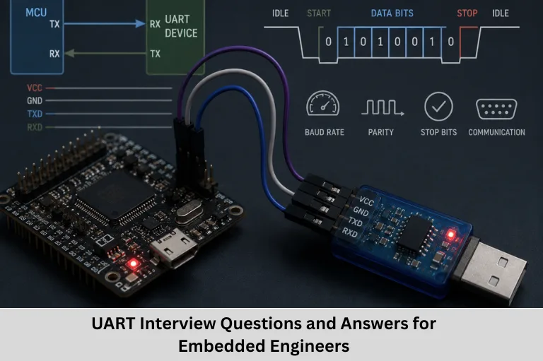
Prepare for UART interviews with 21+ questions and answers covering baud rate, UART frames, parity, buffers, DMA, flow control, errors, SPI and I2C. Embedded Tech Development Academy (ETDA).
- UART Interview Questions and Answers for Embedded Engineers
-
UART Interview Questions and Answers for Embedded Systems
- Introduction to UART Communication
- Why Is UART Important in Embedded Systems?
-
UART Interview Questions and Answers
- Basic UART Interview Questions
- UART Buffer and Flow Control Questions
- UART Error and Frame Questions
-
Advanced UART Interview Questions
- Q14. What is DMA and how is it used with UART?
- Q15. What are different UART modes?
- Q16. What is the difference between UART and SPI?
- Q17. What is the purpose of the UART baud rate?
- Q18. How does flow control work in UART?
- Q19. How can UART communication be secured?
- Q20. What is the purpose of the UART parity bit?
- Q21. What is the role of a UART controller?
- UART Communication Parameters You Should Know
- Common UART Configuration Example
-
Practical UART Interview Tips
- What Should Freshers Know About UART?
- Practical Knowledge Matters
- FAQs
- Is UART synchronous or asynchronous?
- How many wires are required for basic UART communication?
- What is the most common UART configuration?
- Can UART communicate with multiple devices?
- Why is UART important for embedded systems interviews?
- Conclusion
UART Interview Questions and Answers for Embedded Systems
Introduction to UART Communication
UART (Universal Asynchronous Receiver/Transmitter) is one of the most widely used serial communication interfaces in embedded systems. It provides a simple and reliable way to exchange data between a microcontroller, processor, sensor, GPS module, Bluetooth module, GSM module, Wi-Fi module, PC, or other peripheral devices.
Unlike synchronous communication protocols such as SPI and I2C, UART communication does not require a separate clock signal. Instead, the transmitter and receiver agree on communication parameters such as baud rate, data bits, parity, and stop bits. This makes UART particularly useful for point-to-point communication and embedded system debugging.
UART is an important topic for students and professionals preparing for embedded systems interviews, especially for roles involving Embedded C, ARM microcontrollers, STM32, LPC1768, firmware development, Internet of Things (IoT), automotive embedded systems, and hardware-software integration.
Understanding concepts such as UART baud rate, UART frame format, TX and RX pins, parity bit, stop bit, UART buffer, flow control, DMA, framing errors, overrun errors, and serial communication can help candidates answer both basic and technical interview questions confidently.
For students looking for practical embedded systems training, Embedded Tech Development Academy (ETDA) is a Top Embedded Training Institute in Bangalore, offering hands-on learning in embedded programming, microcontrollers, communication protocols, and real-time projects, along with assured placement support.
Why Is UART Important in Embedded Systems?
UART is frequently used because it requires minimal hardware and is relatively easy to configure. A typical UART connection uses:
- TX (Transmit) – Sends serial data.
- RX (Receive) – Receives serial data.
- GND (Ground) – Provides a common electrical reference.
UART is commonly used in:
- Microcontroller-to-PC communication
- GPS modules
- Bluetooth modules
- GSM modules
- Wi-Fi modules
- Debugging and logging
- Industrial control systems
- Internet of Things (IoT) devices
- Automotive electronics
- Embedded development boards
UART Interview Questions and Answers
Basic UART Interview Questions
Q1. What does UART stand for?
UART stands for Universal Asynchronous Receiver/Transmitter. It is a hardware communication interface used for asynchronous serial communication between electronic devices.
Q2. What is UART and how does it work?
UART stands for Universal Asynchronous Receiver/Transmitter. It is a serial communication interface used to transmit and receive data between two devices.
UART sends data one bit at a time without using a separate clock signal. The transmitter and receiver must be configured with compatible communication parameters.
A basic UART connection uses:
- TX for transmitting data
- RX for receiving data
- GND for a common reference
A UART frame generally contains a start bit, data bits, optional parity bit, and stop bit(s).
Q3. What is the difference between UART, SPI, and I2C?
UART, SPI, and I2C are serial communication interfaces, but they differ in their communication methods and hardware requirements.
| Feature | UART | SPI | I2C |
|---|---|---|---|
| Clock | Asynchronous | Synchronous | Synchronous |
| Typical wires | TX, RX | SCLK, MOSI, MISO, CS | SDA, SCL |
| Communication | Point-to-point | Master-slave | Multi-device bus |
| Addressing | No built-in addressing | Chip select | Device address |
| Complexity | Low | Moderate | Moderate |
| Common use | Debugging, modules | Displays, Flash, sensors | Sensors, EEPROM |
UART is simple and convenient for point-to-point communication, while SPI is generally preferred for high-speed peripheral communication and I2C is useful when multiple peripherals share the same two-wire bus.
Q4. What is baud rate in UART communication?
The baud rate represents the signaling rate used for serial communication. In common UART configurations where one symbol represents one bit, it corresponds numerically to the bit rate.
Common UART settings include:
- 9600 baud
- 19200 baud
- 38400 baud
- 57600 baud
- 115200 baud
The transmitter and receiver must use compatible baud-rate settings. The UART baud rate is typically generated from the peripheral clock using a hardware divider or baud-rate generator.
Q5. How do UART transmitter and receiver synchronize data?
UART uses a start bit and stop bit to establish the timing of each frame.
When the UART line is idle, it is normally HIGH. The transmitter starts a frame by sending a LOW start bit. The receiver detects this transition and uses its configured baud-rate timing to sample the incoming data bits.
The frame ends with one or more stop bits, which are normally HIGH.
UART Buffer and Flow Control Questions
Q6. What is a UART buffer?
A UART buffer is temporary storage used to hold data being transmitted or received.
Buffers can be implemented in:
- UART hardware
- RAM/software
- FIFO memory
A software receive buffer, for example, can store incoming bytes until the application is ready to process them. This is particularly useful when data arrives faster than the main application can process it.
Q7. What is flow control in UART?
Flow control regulates the rate of data transmission between two communicating devices to prevent buffer overflow and data loss.
There are two common types:
1. Hardware flow control:
Uses signals such as RTS (Request to Send) and CTS (Clear to Send).
2. Software flow control:
Uses special characters such as XON and XOFF to control transmission.
Flow control becomes especially useful when a receiver cannot process incoming data quickly enough.
Q8. What are the advantages of UART?
Major advantages of UART include:
- Simple hardware implementation
- Low communication overhead
- Easy configuration
- Low cost
- Widely supported by microcontrollers
- Useful for debugging
- Suitable for point-to-point communication
- Works well with many external modules
UART is particularly popular in embedded development because developers can use a serial terminal to monitor debugging messages and system status.
UART Error and Frame Questions
Q9. How can errors occur in UART communication?
UART errors can occur because of:
- Electrical noise
- Signal interference
- Incorrect baud rate
- Incorrect frame configuration
- Clock mismatch
- Poor signal integrity
- Buffer overflow
UART hardware may detect errors such as parity errors, framing errors, and overrun errors.
Parity can help detect certain bit errors, while higher-level communication protocols can use checksums or CRC (Cyclic Redundancy Check) for stronger error detection.
Q10. What is a UART frame?
A UART frame is the complete sequence of bits transmitted for one data character.
A typical UART frame contains:
Start Bit → Data Bits → Optional Parity Bit → Stop Bit(s)
For example, a common 8-N-1 configuration means:
- 8 data bits
- No parity
- 1 stop bit
The start bit identifies the beginning of the frame, while the stop bit indicates its end.
Q11. What is the maximum data rate of UART?
There is no single universal maximum UART data rate. The achievable rate depends on the specific microcontroller, UART peripheral, clock frequency, electrical interface, and communication environment.
For example, at 115200 baud, if 8 data bits are transmitted using an 8-N-1 frame, each character requires 10 bits including the start and stop bits.
Therefore:
115200 ÷ 10 = 11,520 characters per second
The effective payload rate is lower than the raw baud rate because start, parity, and stop bits consume transmission time.
Q12. What are the different UART errors?
Common UART errors include:
1. Framing Error:
Occurs when the receiver does not detect the expected stop bit at the correct time. It can result from baud-rate mismatch, noise, or incorrect frame settings.
2. Parity Error:
Occurs when the received parity does not match the expected parity.
3. Overrun Error:
Occurs when new data arrives before previously received data has been read or moved out of the receive buffer.
4. Noise Error:
Some UART peripherals provide noise/error detection when the received signal is affected by interference.
Error handling may involve discarding invalid data, clearing error flags, requesting retransmission, or using higher-level error-detection mechanisms.
Q13. What is the role of a UART buffer?
A UART buffer temporarily stores transmitted or received data.
For example, when a UART receives bytes continuously, the incoming data can be placed into a receive FIFO or software circular buffer. The CPU or application can process the data later.
Buffers improve reliability by reducing the chance of data loss when the application cannot immediately process every received byte.
Advanced UART Interview Questions
Q14. What is DMA and how is it used with UART?
DMA stands for Direct Memory Access.
DMA allows data to be transferred between a peripheral and memory with minimal CPU involvement.
With UART, DMA can transfer:
UART Receive Register → RAM
or
RAM → UART Transmit Register
This is useful for applications that need to transfer large amounts of serial data efficiently.
Benefits include:
- Reduced CPU usage
- Faster data handling
- Lower interrupt overhead
- Improved system performance
Q15. What are different UART modes?
UART peripherals can support different operating modes depending on the microcontroller.
Common configurations include:
- Asynchronous UART
- Synchronous serial modes on some peripherals
- LIN-related modes on some microcontrollers
- ISO 7816 smart-card modes on selected UART peripherals
The exact modes depend on the microcontroller’s UART peripheral.
For standard embedded communication, asynchronous UART mode is the most commonly used.
Q16. What is the difference between UART and SPI?
UART is normally an asynchronous point-to-point communication interface, while SPI is a synchronous interface that uses a clock.
UART generally uses:
- TX
- RX
- GND
SPI commonly uses:
- SCLK
- MOSI
- MISO
- CS/SS
UART is convenient for modules, debugging, and simple device-to-device communication. SPI is often preferred when higher throughput and synchronous communication are required.
Q17. What is the purpose of the UART baud rate?
The baud rate determines the timing used for serial communication.
The UART peripheral calculates the required timing from its input/peripheral clock and an internal baud-rate generation mechanism.
For reliable communication, both transmitter and receiver should be configured with compatible:
- Baud rate
- Data length
- Parity
- Stop bits
Q18. How does flow control work in UART?
Flow control prevents the transmitter from sending data faster than the receiver can handle.
Hardware flow control may use:
- RTS
- CTS
Software flow control may use:
- XON
- XOFF
Hardware flow control is useful when dedicated control lines are available and high-volume data transmission must be managed efficiently.
Q19. How can UART communication be secured?
UART itself does not provide encryption or authentication. Anyone with physical or electrical access to an exposed UART interface may potentially monitor the transmitted data.
For security-sensitive applications, developers can add:
- Encryption
- Authentication
- Secure boot mechanisms
- Access control
- Physical protection
- Message integrity checks
Security should therefore be implemented at a higher protocol or system level when required.
Q20. What is the purpose of the UART parity bit?
The parity bit is an optional bit used for basic error detection.
Common parity modes include:
- Even parity
- Odd parity
- No parity
With even parity, the parity bit is selected so that the total number of 1s in the protected data plus parity bit is even.
Parity can detect many single-bit errors, but it cannot reliably detect all possible multi-bit errors and does not correct errors.
Q21. What is the role of a UART controller?
The UART controller is the hardware peripheral responsible for managing serial communication.
It generally handles:
- Data transmission
- Data reception
- Baud-rate generation
- Frame configuration
- Parity
- Stop bits
- Error detection
- Interrupt generation
- FIFO/buffering on supported devices
- DMA requests on supported devices
The CPU configures the UART through control and status registers and exchanges data through UART data registers or buffers.
UART Communication Parameters You Should Know
Baud Rate
The baud rate determines the timing of serial communication. Both communicating devices must use compatible settings.
Data Bits
Common UART configurations use 7 or 8 data bits, while some hardware supports other configurations.
Parity
Parity can be configured as:
- None
- Even
- Odd
Stop Bits
UART commonly supports:
- 1 stop bit
- 1.5 stop bits in some configurations
- 2 stop bits
TX and RX
TX is used to transmit serial data, while RX receives serial data.
One device’s TX is generally connected to the other device’s RX.
Common UART Configuration Example
What Does 8-N-1 Mean?
One of the most common UART configurations is 8-N-1.
It means:
- 8 = 8 data bits
- N = No parity
- 1 = 1 stop bit
The frame can therefore be represented as:
Start Bit → 8 Data Bits → Stop Bit
This configuration is frequently used for debugging and communication with embedded modules.
Practical UART Interview Tips
What Should Freshers Know About UART?
Candidates preparing for embedded systems interviews should understand more than the definition of UART.
Be prepared to explain:
- UART working principle
- TX and RX
- Baud rate
- UART frame
- Start and stop bits
- Data bits
- Parity
- UART interrupts
- FIFO
- Circular buffers
- Flow control
- DMA
- UART errors
- UART vs SPI
- UART vs I2C
Practical Knowledge Matters
Interviewers may also ask candidates to write basic Embedded C UART programs, configure a UART peripheral, transmit a string, receive a character, or troubleshoot communication problems.
Example Interview Scenario
Interviewer: Your UART is transmitting correctly, but the receiver gets garbage characters. What would you check?
Answer:
I would first check:
- Baud-rate configuration
- TX/RX wiring
- Common ground
- Data-bit configuration
- Parity configuration
- Stop-bit configuration
- Clock configuration
- Voltage-level compatibility
- Signal integrity
- UART peripheral configuration
This type of troubleshooting approach demonstrates practical embedded-system knowledge.
FAQs
Is UART synchronous or asynchronous?
UART is normally an asynchronous serial communication interface. It does not require a separate clock line between the transmitter and receiver.
How many wires are required for basic UART communication?
Basic UART communication typically requires TX, RX, and GND. For one-way communication, only one data line plus a common ground may be needed.
What is the most common UART configuration?
8-N-1 is one of the most widely used UART configurations: 8 data bits, no parity, and 1 stop bit.
Can UART communicate with multiple devices?
Standard UART is generally designed for point-to-point communication. Multi-device communication requires additional hardware or a higher-level protocol designed for that purpose.
Why is UART important for embedded systems interviews?
UART is one of the fundamental communication interfaces used in embedded systems. Understanding UART helps candidates demonstrate knowledge of serial communication, microcontroller peripherals, interrupts, buffers, DMA, error handling, and Embedded C programming.
Conclusion
UART remains one of the most important serial communication interfaces in embedded systems because of its simple architecture, low hardware complexity, ease of configuration, and widespread microcontroller support. From basic debugging through a serial terminal to communication with GPS, Bluetooth, GSM, Wi-Fi, sensors, industrial equipment, and other embedded modules, UART continues to play an important role in firmware development.
For embedded engineers, it is important to understand not only the definition of UART but also practical concepts such as baud rate calculation, UART frame format, TX/RX communication, parity, stop bits, FIFO buffers, interrupts, DMA, flow control, framing errors, parity errors, overrun errors, and UART troubleshooting.
These concepts frequently appear in Embedded C and embedded systems interview questions, particularly for freshers and engineers applying for firmware and microcontroller development roles.
If you want to build practical skills in UART, SPI, I2C, CAN, Embedded C, ARM microcontrollers, RTOS, STM32, LPC1768, and embedded system design, Embedded Tech Development Academy (ETDA) is a Top Embedded Training Institute in Bangalore focused on practical, industry-oriented embedded systems training. Embedded Tech Development Academy (ETDA) provides hands-on project learning and assured placement support to help learners prepare for real-world embedded engineering opportunities.
Learning UART is therefore not just about answering an interview question—it is an essential step toward understanding embedded communication protocols, firmware development, microcontroller programming, and real-time embedded systems.
Author: ETDA Trainers
Experience: 10+ Years of Industry Experience in Embedded Systems, IoT, and Embedded C Programming