
SPI Communication Protocol: Working, Modes, Advantages & Applications
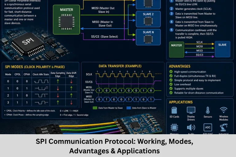
Learn SPI communication protocol, its working, signals, SPI modes, timing, master-slave architecture, Embedded C programming, applications, debugging, and SPI vs I2C. Embedded Tech Development Academy (ETDA).
- SPI Communication Protocol: Working, Modes, Advantages & Applications
-
Understanding SPI Communication Protocol: A Complete Technical Guide
- What Is SPI Communication?
- SPI Bus Architecture
- How SPI Communication Works
- SPI Clock Modes
- Single and Multiple SPI Peripherals
- SPI vs I2C vs UART
- SPI Registers in Microcontrollers
- SPI Registers
- SPI Embedded C Programming
- Applications of SPI
- SPI Debugging and Troubleshooting
- SPI Troubleshooting
- Advanced SPI Concepts
- Advantages and Disadvantages of SPI
- Frequently Asked Questions
- Conclusion
Understanding SPI Communication Protocol: A Complete Technical Guide
The Serial Peripheral Interface (SPI) is one of the most widely used synchronous serial communication protocols in embedded systems. It provides a simple and high-speed method for transferring data between a microcontroller and peripheral devices such as sensors, EEPROMs, Flash memory, ADCs, DACs, SD cards, LCDs, OLED displays, RTCs, and wireless modules.
SPI is particularly useful when an embedded application requires high-speed data transfer, low communication overhead, deterministic timing, full-duplex communication, and direct peripheral interfacing. Unlike UART, SPI uses a clock generated by the master to synchronize data transmission. Unlike I2C, SPI generally does not use device addressing; instead, individual chip-select lines are commonly used to select peripherals.
For embedded engineers, understanding SPI protocol, SPI bus architecture, MOSI, MISO, SCK, CS, CPOL, CPHA, SPI timing, master-slave communication, shift registers, Embedded C programming, and microcontroller peripherals is essential for developing reliable hardware-software interfaces.
Embedded Tech Development Academy (ETDA) emphasizes practical embedded systems training where communication protocols such as SPI, I2C, UART, CAN, and USB are studied from both hardware and software perspectives. As a Top Embedded Training Institute in Bangalore, Embedded Tech Development Academy (ETDA) focuses on practical technical skills and provides assured placement support to career-focused learners.
Learning SPI at Embedded Tech Development Academy (ETDA), a Top Embedded Training Institute in Bangalore, can help engineers understand peripheral interfacing, register-level programming, debugging with logic analyzers, and real-time communication. This practical approach, combined with assured placement support, can help learners prepare for embedded software and firmware development roles.
What Is SPI Communication?
SPI (Serial Peripheral Interface) is a synchronous, serial, full-duplex communication protocol used primarily for short-distance communication between a controller and peripheral devices.
SPI normally uses four signals:
- MOSI — Master Out Slave In
- MISO — Master In Slave Out
- SCK/SCLK — Serial Clock
- CS/SS — Chip Select/Slave Select
Important SPI Characteristics
| Feature | SPI |
|---|---|
| Communication | Synchronous |
| Duplex | Full duplex |
| Clock | Required |
| Typical signals | MOSI, MISO, SCK, CS |
| Addressing | No built-in addressing |
| Speed | High |
| Distance | Generally short-range |
Why SPI Is Fast
SPI does not require start and stop bits like asynchronous UART communication. It also does not require an addressing phase like I2C. Data is shifted directly according to the clock, allowing efficient transfers.
SPI Bus Architecture
SPI generally follows a controller-peripheral architecture.
SPI Bus Signals
| Signal | Full Form | Direction |
|---|---|---|
| MOSI | Master Out Slave In | Master → Peripheral |
| MISO | Master In Slave Out | Peripheral → Master |
| SCK | Serial Clock | Master → Peripheral |
| CS/SS | Chip Select | Master → Peripheral |
Master Responsibilities
The SPI master or controller:
- Generates the clock
- Selects the peripheral
- Initiates communication
- Determines clock frequency
- Controls the SPI mode
Peripheral Responsibilities
The selected peripheral:
- Receives the clock
- Receives data through MOSI
- Sends data through MISO
- Responds according to its device-specific SPI protocol
How SPI Communication Works
SPI transfers data using shift registers.
Step-by-Step SPI Transfer
Step 1: Peripheral Selection
The controller pulls the appropriate CS line to its active level, commonly LOW.
Step 2: Clock Generation
The controller generates SCK pulses according to the configured SPI frequency and mode.
Step 3: Data Transmission
Data is shifted from the controller to the peripheral through MOSI.
Step 4: Data Reception
At the same time, data can be shifted from the peripheral through MISO.
Step 5: Transfer Completion
After the required number of clock cycles, the controller deasserts CS.
Full-Duplex Operation
SPI is full duplex because data can move in both directions during the same clock cycles.
For an 8-bit transfer, eight clock pulses normally shift eight bits in and eight bits out.
Shift Register Concept
Both communicating devices can use shift registers. During each clock cycle:
- One bit is shifted out.
- One bit is shifted in.
After eight clock cycles, an 8-bit transfer is complete.
SPI Clock Modes
SPI has four standard clock modes determined by CPOL (Clock Polarity) and CPHA (Clock Phase).
| Mode | CPOL | CPHA |
|---|---|---|
| Mode 0 | 0 | 0 |
| Mode 1 | 0 | 1 |
| Mode 2 | 1 | 0 |
| Mode 3 | 1 | 1 |
Clock Polarity — CPOL
CPOL determines the idle state of SCK.
- CPOL = 0: Clock is LOW when idle.
- CPOL = 1: Clock is HIGH when idle.
Clock Phase — CPHA
CPHA determines which clock edge is used for data sampling and shifting.
The exact edge relationship depends on the selected SPI mode and controller implementation.
Why SPI Mode Matters
If the controller and peripheral use different CPOL/CPHA settings, the receiver may sample data at the wrong time, resulting in corrupted or apparently random data.
Therefore, the peripheral datasheet should always be checked before configuring SPI.
Single and Multiple SPI Peripherals
Single Peripheral
A simple SPI system can connect one controller to one peripheral using:
MOSI + MISO + SCK + CS
Multiple Peripherals
Several SPI peripherals can share MOSI, MISO, and SCK.
Typically, each peripheral receives its own CS line:
             ┌── Peripheral 1
             │     CS1
Controller ──┼── Peripheral 2
             │     CS2
             └── Peripheral 3
                   CS3
Chip-Select Management
Only the intended peripheral should be selected during a transaction. Proper CS timing is important, particularly when several devices share the same SPI bus.
SPI vs I2C vs UART
| Feature | SPI | I2C | UART |
|---|---|---|---|
| Clock | Yes | Yes | No |
| Duplex | Full duplex | Typically half duplex | Full duplex |
| Typical wires | 4+ | 2 | 2 |
| Addressing | No built-in addressing | Yes | No |
| Speed | High | Moderate to high | Moderate to high |
| Chip select | Usually required | Not required | Not required |
| Main use | Fast peripherals | Multi-device bus | Serial links |
When Should SPI Be Used?
SPI is a strong choice when the system needs high throughput, low protocol overhead, and short-distance communication between a controller and peripherals.
SPI Registers in Microcontrollers
Hardware SPI peripherals commonly contain control, status, and data registers. Their names vary between microcontroller families.
Example AVR SPI Registers
Some AVR microcontrollers provide registers such as:
SPI Registers
| Register | Purpose |
|---|---|
| SPCR | SPI Control Register |
| SPSR | SPI Status Register |
| SPDR | SPI Data Register |
The exact register definitions depend on the selected AVR device.
SPI Embedded C Programming
A simplified AVR-style SPI transmission routine can look like this:
SPI Write Function
void SPI_Write(unsigned char data)
{
    SPDR = data;

    while (!(SPSR & (1 << SPIF)))
    {
        /* Wait for transfer completion */
    }
}
SPI Read Function
Because SPI simultaneously transmits and receives, a controller commonly transmits a dummy byte when it wants to clock data from a peripheral.
unsigned char SPI_Read(void)
{
    SPDR = 0xFF;

    while (!(SPSR & (1 << SPIF)))
    {
        /* Wait */
    }

    return SPDR;
}
SPI Initialization
A basic AVR-style configuration may include:
void SPI_Init(void)
{
    DDRB |= (1 << MOSI) |
            (1 << SCK)  |
            (1 << SS);

    SPCR = (1 << SPE) |
           (1 << MSTR) |
           (1 << SPR0);
}
Actual pin assignments, clock settings, and register configurations depend on the specific microcontroller.
Applications of SPI
Sensor Interfacing
SPI is commonly used with:
- IMUs
- Temperature sensors
- Pressure sensors
- Accelerometers
- Gyroscopes
- ADCs
Display Communication
SPI interfaces are frequently used with TFT LCDs, OLEDs, and other graphical displays.
Memory Devices
SPI Flash and EEPROM devices use SPI-style interfaces for reading and writing non-volatile data.
SD Cards and Wireless Modules
SPI modes are commonly available for SD cards and various radio or wireless modules.
Embedded System Applications
SPI is found in:
- Automotive electronics
- Industrial controllers
- Medical electronics
- Robotics
- Internet of Things (IoT) devices
- Consumer electronics
SPI Debugging and Troubleshooting
SPI problems can often be identified by examining signals with a logic analyzer or oscilloscope.
Common Problems
SPI Troubleshooting
| Problem | Possible Cause |
|---|---|
| No communication | Incorrect wiring or CS |
| Corrupted data | Incorrect CPOL/CPHA |
| Missing response | Peripheral not selected |
| Unstable transfer | Excessive clock frequency |
| Random values | Incorrect timing or protocol |
Debugging Checklist
Check:
- Common ground.
- MOSI and MISO connections.
- CS polarity and timing.
- SPI clock frequency.
- CPOL and CPHA.
- Data-bit order.
- Peripheral initialization sequence.
- Logic analyzer waveform.
Logic Analyzer
A logic analyzer can capture CS, SCK, MOSI, and MISO and decode the SPI transaction. This makes it possible to determine whether the controller is transmitting the expected command and whether the peripheral is responding correctly.
Advanced SPI Concepts
DMA-Based SPI
Microcontrollers with DMA controllers can transfer large blocks of SPI data without requiring the CPU to handle every byte. This reduces CPU overhead and is useful for displays, storage, ADCs, and high-throughput applications.
Dual and Quad SPI
Some memory devices use additional data lines to increase throughput. Dual SPI and Quad SPI (QSPI) can transfer multiple bits per clock cycle.
Advantages and Disadvantages of SPI
Advantages
- High data-transfer speed
- Full-duplex communication
- Simple protocol
- Low overhead
- Flexible frame sizes
- Suitable for real-time peripheral access
Disadvantages
- Requires more wires than I2C
- No built-in addressing
- No standard acknowledgment mechanism
- CS lines increase with multiple peripherals
- Generally intended for short-distance communication
Frequently Asked Questions
What is SPI communication?
SPI, or Serial Peripheral Interface, is a synchronous serial communication protocol commonly used for high-speed communication between a microcontroller and peripheral devices.
What are the four main SPI signals?
The four commonly used SPI signals are MOSI, MISO, SCK, and CS/SS. MOSI carries controller-to-peripheral data, MISO carries peripheral-to-controller data, SCK provides the clock, and CS selects the peripheral.
What are SPI Mode 0, 1, 2, and 3?
SPI modes are combinations of CPOL and CPHA. Mode 0 is CPOL=0 and CPHA=0, Mode 1 is CPOL=0 and CPHA=1, Mode 2 is CPOL=1 and CPHA=0, and Mode 3 is CPOL=1 and CPHA=1.
Is SPI faster than I2C?
SPI can generally provide higher throughput and lower protocol overhead than I2C, although the actual speed depends on the microcontroller, peripheral, clock configuration, PCB design, and device specifications.
Where is SPI used in embedded systems?
SPI is widely used for sensors, ADCs, DACs, EEPROMs, Flash memory, SD cards, TFT displays, OLED displays, RTCs, wireless modules, and other high-speed peripheral interfaces.
Conclusion
SPI is a high-speed, synchronous serial communication protocol that provides an efficient interface between microcontrollers and peripheral devices. Its MOSI, MISO, SCK, and CS signals, combined with full-duplex data transfer and configurable clock timing, make it highly suitable for embedded hardware integration.
Understanding SPI requires knowledge of SPI architecture, master-peripheral communication, chip-select handling, shift registers, CPOL, CPHA, timing, SPI registers, Embedded C programming, DMA, and logic-analyzer debugging. Engineers must also carefully follow the peripheral datasheet because SPI timing, command formats, maximum clock rates, CS behavior, and data order can vary between devices.
SPI remains important in automotive systems, robotics, industrial automation, Internet of Things (IoT), medical electronics, displays, memory devices, sensors, and embedded controllers. For engineers working with microcontrollers, firmware, and real-time hardware interfaces, SPI is an essential communication protocol.
Embedded Tech Development Academy (ETDA) provides practical training in embedded systems, Embedded C, microcontrollers, communication protocols, Linux, and firmware development. As a Top Embedded Training Institute in Bangalore, Embedded Tech Development Academy (ETDA) focuses on hands-on technical learning and offers assured placement support for career-focused learners.
For students and professionals looking to strengthen their embedded communication and firmware skills, Embedded Tech Development Academy (ETDA), a Top Embedded Training Institute in Bangalore, provides practical exposure to protocols such as SPI along with assured placement support. Developing strong SPI fundamentals can help engineers confidently interface sensors, displays, memories, ADCs, DACs, and other peripherals in real-world embedded systems.
Author: ETDA Trainers
Experience: 10+ Years of Industry Experience in Embedded Systems, IoT, and Embedded C Programming