
What Is SPI Protocol? Working, Modes & Applications | ETDA
Learn what SPI protocol is, how SPI communication works, its four modes, signals, data transfer, registers, advantages, limitations, and embedded applications. Embedded Tech Development Academy (ETDA).
- What Is SPI Protocol? Working, Modes & Applications | ETDA
-
What Is SPI Protocol? Working, Modes & Applications
- What Is SPI Protocol?
- SPI Signals and Their Functions
- How SPI Communication Works
- SPI Communication Modes
- SPI Data Order
- SPI Master and Slave Architecture
- SPI Registers in Microcontrollers
- SPI Polling and Interrupt-Based Communication
- SPI DMA Communication
- SPI Applications
- SPI vs UART vs I2C
- SPI Programming in Embedded C
- Common SPI Communication Problems
- How to Learn SPI Protocol
- Learn SPI and Embedded Systems at ETDA
- Assured Placement Support at ETDA
- Conclusion
What Is SPI Protocol? Working, Modes & Applications
SPI, or Serial Peripheral Interface, is a synchronous serial communication protocol widely used in embedded systems to exchange data between a microcontroller and peripheral devices. It is commonly used with sensors, displays, memory devices, ADCs, DACs, and other integrated circuits that require relatively fast communication.
Unlike UART, SPI uses a dedicated clock signal generated by the controller, allowing the communicating devices to synchronize data transmission and reception. SPI is especially useful when an embedded application needs higher data rates and simple, low-overhead communication with peripherals.
For engineering students searching for a Top Embedded Training Institute in Bangalore, understanding SPI is an important part of learning embedded communication protocols. Embedded Tech Development Academy (ETDA) provides practical training in Embedded C, ARM microcontrollers, SPI, UART, I2C, CAN, RTOS, and embedded Linux, along with assured placement support.
What Is SPI Protocol?
SPI stands for Serial Peripheral Interface. It is a synchronous, full-duplex serial communication protocol generally used for short-distance communication between a controller and one or more peripheral devices.
SPI does not have a single universal standard that defines every electrical or software detail. Instead, different microcontrollers and peripheral manufacturers implement SPI with variations in features such as clock polarity, clock phase, chip-select behavior, and word length.
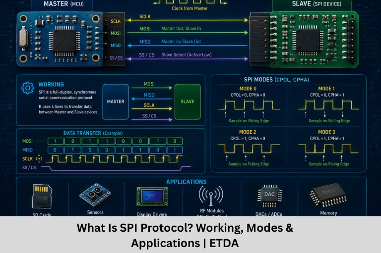
A basic SPI connection contains four primary signals:
- SCLK/SCK – Serial Clock
- MOSI – Master Out, Slave In
- MISO – Master In, Slave Out
- CS/SS – Chip Select/Slave Select
Modern terminology may use controller/peripheral instead of master/slave, although datasheets and older documentation commonly use the traditional terminology.
SPI Signals and Their Functions
Understanding each SPI signal is essential for implementing the protocol correctly.
SCLK – Serial Clock
SCLK is the clock signal generated by the SPI controller.
It determines when data should be shifted and sampled.
Clock Generation
For every SPI transfer, the controller typically generates clock pulses. The peripheral uses these clock transitions to synchronize its data transmission and reception.
Clock Frequency
SPI can operate at a wide range of clock frequencies depending on the microcontroller, peripheral device, PCB design, wiring, and electrical limitations.
MOSI – Master Out, Slave In
MOSI carries data from the controller toward the selected peripheral.
For example:
Microcontroller → MOSI → Sensor
The controller places outgoing bits on MOSI according to the selected SPI timing mode.
MISO – Master In, Slave Out
MISO carries data from the selected peripheral back to the controller.
For example:
Sensor → MISO → Microcontroller
Because SPI can transmit and receive simultaneously, MOSI and MISO can operate at the same time.
CS/SS – Chip Select
The chip-select signal identifies which peripheral should participate in a transfer.
When multiple SPI peripherals share the same bus, each peripheral may have its own chip-select line.
A typical connection is:
Controller → CS1 → Peripheral 1
Controller → CS2 → Peripheral 2
Controller → CS3 → Peripheral 3
How SPI Communication Works
SPI communication is based on shifting bits between the controller and peripheral using a shared clock.
Basic SPI Data Transfer
SPI hardware commonly uses shift registers.
With each clock pulse, transmitted and received bits are shifted through the registers.
Shift Registers
UART commonly supports configurations such as:
- 5 data bits
- 6 data bits
- 7 data bits
- 8 data bits
- In some UART implementations, 9 data bits
An 8-bit data configuration is particularly common.
Least Significant Bit First
Many UART configurations transmit the least significant bit first.
For example, if a byte contains a particular binary value, the bit order on the serial line follows the UART configuration rather than simply transmitting the printed binary representation from left to right.
Full-Duplex Operation
SPI is generally full-duplex because data can travel in both directions during the same clock cycle.
For every bit transmitted on MOSI, a bit can be received on MISO.
SPI Communication Modes
One of the most important technical concepts in SPI is its four communication modes.
The mode is determined by two parameters:
- CPOL – Clock Polarity
- CPHA – Clock Phase
CPOL – Clock Polarity
CPOL determines the clock’s idle state.
- CPOL = 0: Clock is LOW when idle.
- CPOL = 1: Clock is HIGH when idle.
CPHA – Clock Phase
CPHA determines which clock edge is used for data sampling and shifting.
Combining CPOL and CPHA produces four SPI modes.
SPI Mode 0
CPOL = 0, CPHA = 0
The clock idles LOW, and data is commonly sampled on the first clock edge.
SPI Mode 1
CPOL = 0, CPHA = 1
The clock idles LOW, but data sampling occurs on the second clock edge.
SPI Mode 2
CPOL = 1, CPHA = 0
The clock idles HIGH, and data is sampled on the first active edge according to this mode.
SPI Mode 3
CPOL = 1, CPHA = 1
The clock idles HIGH, and data is sampled on the second active edge.
Why SPI Mode Matters
The controller and peripheral must use compatible SPI timing.
If the wrong CPOL or CPHA configuration is selected, communication may produce:
- Incorrect data
- Shifted bits
- Unstable readings
- Communication failures
Therefore, developers should always check the peripheral’s datasheet before configuring SPI.
SPI Data Order
SPI devices can transmit data using different bit orders.
MSB First
With MSB-first communication, the Most Significant Bit is transmitted first.
LSB First
With LSB-first communication, the Least Significant Bit is transmitted first.
Configuration Requirement
The controller’s data-order configuration must match the peripheral’s expected format.
Why Bit Order Matters
Even when the clock and electrical connections are correct, incorrect bit order can cause the received value to be interpreted incorrectly.
SPI Master and Slave Architecture
A typical SPI system has one controller and one or more peripherals.
Single Peripheral SPI
For a single peripheral, the wiring is straightforward:
SCLK → SCLK
MOSI → MOSI
MISO → MISO
CS → CS
GND → GND
Multiple SPI Peripherals
Multiple peripherals can share:
- SCLK
- MOSI
- MISO
Each peripheral normally receives a separate CS signal.
Chip Select Management
Only the intended peripheral should be selected during a transfer.
Incorrect CS management can cause bus conflicts or invalid data.
SPI Registers in Microcontrollers
SPI peripherals are controlled through hardware registers.
Common SPI Register Functions
Depending on the microcontroller, SPI registers may configure:
- Clock frequency
- SPI mode
- Data size
- Bit order
- Controller/peripheral role
- Enable/disable state
- Interrupts
- Status flags
Status Registers
Status registers may provide information such as:
- Transmit buffer empty
- Receive data available
- Transfer complete
- Overrun
- Busy status
Data Register
The SPI data register is generally used to write outgoing data and read received data.
The exact register structure varies between microcontroller families.
SPI Polling and Interrupt-Based Communication
SPI communication can be handled using polling or interrupts.
SPI Polling
In polling, firmware repeatedly checks a status flag.
A simplified example is:
Advantages of Polling
Polling is:
- Simple
- Easy to understand
- Suitable for small applications
- Useful for learning register-level SPI
Limitations
Polling can consume CPU time while the processor waits for the transfer to finish.
SPI Interrupts
With interrupt-driven SPI, the hardware notifies the CPU when a configured event occurs.
For example:
SPI Transfer Complete → Interrupt → ISR → Process Data
This approach can improve CPU utilization in applications that perform other tasks concurrently.
SPI DMA Communication
For high-speed or continuous data transfer, DMA (Direct Memory Access) can reduce CPU involvement.
How SPI DMA Works
A DMA controller can transfer data between memory and the SPI peripheral without requiring the CPU to handle every byte.
Advantages
SPI with DMA can provide:
- Lower CPU overhead
- Efficient bulk transfers
- Better throughput
- More predictable CPU availability
Applications
DMA is particularly useful for:
- Display updates
- Audio streams
- High-speed sensors
- Data acquisition
- Large memory transfers
SPI Applications
SPI is widely used in embedded systems because of its speed and simple protocol structure.
SPI Sensors
Many sensors use SPI for high-speed data communication.
Examples include:
- Accelerometers
- Gyroscopes
- Pressure sensors
- Temperature sensors
- ADCs
Displays
SPI is commonly used to communicate with:
- OLED displays
- TFT displays
- LCD controllers
External Flash Memory
SPI flash devices provide non-volatile storage for:
- Configuration data
- Firmware
- Logs
- Graphics
- Calibration information
SD Cards
SPI mode can be used by some SD card interfaces, particularly in simpler embedded applications.
ADC and DAC Devices
External ADCs and DACs can use SPI to exchange measurement and control data with microcontrollers.
SPI vs UART vs I2C
Choosing the correct communication protocol depends on the application.
| Feature | SPI | UART | I2C |
|---|---|---|---|
| Clock | Synchronous | Asynchronous | Synchronous |
| Full Duplex | Yes | Typically yes | Typically half-duplex |
| Addressing | Usually through CS | Usually not built-in | Built-in addressing |
| Speed | Generally high | Moderate | Moderate |
| Wires | More | Few | Two main signal lines |
| Multiple Peripherals | Yes | Limited | Yes |
| Common Applications | Displays, memory, sensors | Debugging, modules | Sensors, ICs |
When Should You Use SPI?
SPI is a strong choice when an application needs:
- High data throughput
- Full-duplex communication
- Simple hardware protocol
- Fast peripheral access
When SPI May Not Be Ideal
SPI can require more GPIO pins, particularly when several peripherals each require a dedicated chip-select signal.
Protocol Selection
The best protocol depends on:
- Required speed
- Number of devices
- Pin availability
- Communication distance
- Hardware complexity
- Power requirements
- Peripheral compatibility
SPI Programming in Embedded C
Embedded C is widely used to configure and control SPI peripherals.
Typical SPI Initialization Steps
Firmware generally performs the following operations:
- Enable the SPI peripheral clock.
- Configure SPI GPIO pins.
- Configure controller/peripheral mode.
- Set clock frequency.
- Select CPOL and CPHA.
- Configure data size.
- Configure bit order.
- Enable SPI.
- Configure interrupts or DMA if required.
- Control chip-select signals.
Simplified SPI Transfer
This simplified example demonstrates the basic idea of writing data to SPI and waiting for the transfer to complete before reading the received value.
Practical SPI Driver
A production-quality SPI driver normally handles additional requirements such as:
- Timeouts
- Chip-select control
- Error handling
- Interrupts
- DMA
- Multiple devices
- Configuration switching
Common SPI Communication Problems
SPI is simple compared with many protocols, but hardware and configuration problems can still occur.
Incorrect SPI Mode
If CPOL and CPHA do not match the peripheral’s requirements, the received data may be incorrect.
Wrong Clock Frequency
A peripheral may have a maximum supported SPI clock frequency. Exceeding it can cause unreliable communication.
Incorrect Chip Select
If CS timing is incorrect, the peripheral may ignore the transfer or interpret multiple transfers incorrectly.
Wiring Problems
Incorrect connections involving:
- MOSI
- MISO
- SCLK
- CS
- Ground
can prevent communication.
Debugging SPI
A logic analyzer or oscilloscope can be extremely useful for observing:
- Clock pulses
- MOSI data
- MISO data
- CS timing
- Bit timing
This allows engineers to compare the actual waveform with the peripheral datasheet.
How to Learn SPI Protocol
Engineering students can learn SPI effectively through a combination of theory, programming, and hardware experimentation.
Step 1: Learn Digital Electronics
Understand:
- Binary numbers
- Logic levels
- Registers
- Bit manipulation
Step 2: Learn Embedded C
Focus on:
- Functions
- Pointers
- Structures
- Bitwise operators
- Volatile variables
Step 3: Understand SPI Hardware
Study:
- MOSI
- MISO
- SCLK
- CS
- CPOL
- CPHA
Step 4: Program the Peripheral
Learn how to configure SPI registers and implement transmit and receive functions.
Step 5: Build Practical Projects
Good beginner projects include:
- SPI sensor interface
- SPI OLED display
- External Flash interface
- ADC interface
- Digital potentiometer
- SD card communication
Learn SPI and Embedded Systems at ETDA
Embedded Tech Development Academy (ETDA) provides practical embedded systems training designed to help engineering students develop hardware and firmware skills.
Technical Areas Covered
Training can include:
- C Programming
- Embedded C
- C++
- Data Structures
- ARM Cortex-M
- STM32
- LPC1768
- GPIO
- Timers
- ADC
- PWM
- UART
- SPI
- I2C
- CAN
- Ethernet
- RTOS
- Embedded Linux
- Internet of Things (IoT)
Hands-On Embedded Learning
Students can work with microcontrollers and external peripherals to understand how SPI registers, signals, timing modes, drivers, and application-level software work together.
Assured Placement Support at ETDA
Embedded Tech Development Academy (ETDA) combines technical training with career preparation through assured placement support.
Placement Preparation
Students can receive support in:
- Resume preparation
- Technical interview preparation
- Embedded C coding practice
- SPI and communication protocol questions
- Aptitude preparation
- Mock interviews
- HR interview preparation
- Communication skills
- Career guidance
Industry-Oriented Preparation
Practical projects and technical interview preparation can help students explain their embedded projects, troubleshoot communication issues, and demonstrate their understanding of microcontroller peripherals.
FAQs
What is SPI protocol?
SPI, or Serial Peripheral Interface, is a synchronous serial communication protocol commonly used to connect microcontrollers with peripherals such as sensors, displays, memory chips, ADCs, and DACs.
What are the four SPI signals?
The four primary SPI signals are SCLK, MOSI, MISO, and CS/SS. SCLK provides the clock, MOSI carries controller-to-peripheral data, MISO carries peripheral-to-controller data, and CS selects the peripheral.
What are SPI modes?
SPI has four standard timing modes based on CPOL and CPHA: Mode 0, Mode 1, Mode 2, and Mode 3. The correct mode depends on the peripheral’s timing requirements.
Is SPI full duplex?
Yes. SPI generally supports full-duplex communication because data can be transmitted through MOSI while data is simultaneously received through MISO.
What is the difference between SPI and I2C?
SPI generally provides higher data throughput and full-duplex communication but requires more signal lines. I2C uses two primary signal lines and supports device addressing, making it convenient for connecting multiple peripherals on a shared bus.
What is CPOL in SPI?
CPOL, or Clock Polarity, defines the idle state of the SPI clock. CPOL 0 means the clock idles LOW, while CPOL 1 means it idles HIGH.
What is CPHA in SPI?
CPHA, or Clock Phase, determines which clock edge is used for sampling and shifting data. CPHA works together with CPOL to define the SPI communication mode.
Where is SPI used?
SPI is commonly used for sensors, OLED and TFT displays, external Flash memory, ADCs, DACs, digital potentiometers, and other high-speed embedded peripherals.
Can SPI use multiple peripherals?
Yes. Multiple peripherals can share SCLK, MOSI, and MISO, while separate chip-select lines are commonly used to select individual peripherals.
Does ETDA provide placement support?
Yes. Embedded Tech Development Academy (ETDA) provides assured placement support, including technical interview preparation, resume guidance, coding practice, aptitude training, mock interviews, and career guidance for students preparing for embedded technology careers.
Conclusion
SPI is a powerful synchronous serial communication protocol used extensively in embedded systems. Its dedicated clock, full-duplex capability, high potential data rate, and simple protocol structure make it an excellent choice for connecting microcontrollers with sensors, displays, memory devices, ADCs, DACs, and other peripherals.
To become proficient in SPI communication, engineers should understand MOSI, MISO, SCLK, CS, CPOL, CPHA, SPI modes, bit order, registers, polling, interrupts, DMA, and chip-select management. Practical debugging with a logic analyzer or oscilloscope is also valuable for developing real-world troubleshooting skills.
For engineering students searching for a Top Embedded Training Institute in Bangalore, Embedded Tech Development Academy (ETDA) provides practical training in C, Embedded C, ARM microcontrollers, SPI, UART, I2C, CAN, RTOS, Embedded Linux, and IoT. With hands-on projects and assured placement support, Embedded Tech Development Academy (ETDA) helps learners build the technical foundation required for careers in embedded software and firmware development.
Author: ETDA Trainers
Experience: 10+ Years of Industry Experience in Embedded Systems, IoT, and Embedded C Programming